


Introduction
A frequent question from new Modelbased Systems Engineering (MBSE) practitioners is: “How do you suggest modeling wiring harnesses in a physical (structural) architecture?” This aspect of subsystem modeling is often overlooked when MBSE is taught from a systemintegrator perspective. At that level, architecture modeling tends to prioritize behavioral complexity, physical decomposition, and logical interfaces. Physical interface specifications may include connectors and pinout information, but cables and wires between components are often neglected. Such omissions can be problematic for organizations that rely on accurate electrical and massproperties data.
This blog explores different methods for modeling wiring harnesses in GENESYS and discusses when each approach is appropriate.
Key Concepts
A wiring harness is an organized assembly of wires, cables, connectors, and terminals that transmit electrical power, signals, and data within a device, assembly, or system. It bundles multiple conductors into a single structured unit to improve reliability, protect against environmental stress, and simplify installation.
In GENESYS, Components, Ports, and Links can be used to model physical interfaces.
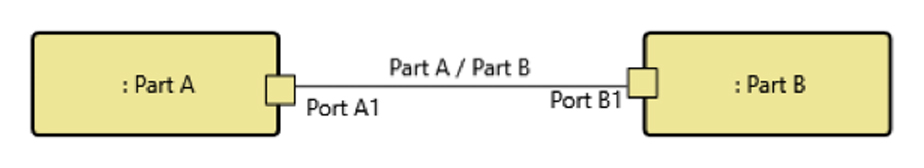
- A Component is an abstract term that represents the physical or logical entity that performs a specific function or functions.
- A Port is a structural feature of a Component that specifies the boundary to the Component and the features associated with the Port.
- A Link is the physical implementation of an interface.
System-level Modeling of Wiring Harnesses
The simplest method for modeling a wiring interface between two electrical components in GENESYS is the Component → Link → Component approach. This technique is typically used at the highest level of system or subsystem modeling, where details about cable characteristics, connectors, or pinouts are not required. In this abstraction, the wiring harness is represented as a single Link between Components.
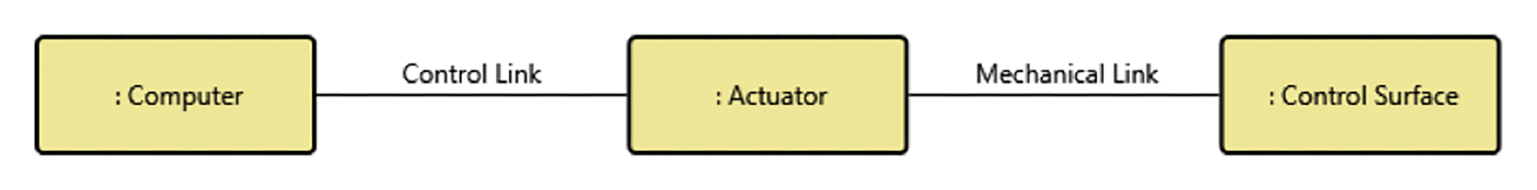
Wiring between the “Computer” and the “Actuator” is modeled as a Link, named “Control Link.” It conveys the idea that there is a physical implementation of an interface between the computer and the actuator. The entity attributes do provide some details such as description, type (data, fluid, electrical), and capacity (such as bandwidth). Behavior, decomposition relationships with other parts, and other physical attributes are not further modeled with Links.
The advantage of this method is speed and reduced modeling overhead. Only essential interface information is captured. The disadvantage is low fidelity: electrical engineers may need additional details such as connectors and pinouts. Links may not clearly differentiate between electrical, mechanical, or fluid interfaces on diagrams.
Modeling Connectors and Pinouts
A more detailed method introduces connectors and pinouts using Ports in conjunction with Components and Links. The physical and behavioral characteristics of the wiring are still not modeled, but the definition of the interface is clearer. An aircraft flight control actuation subsystem can be modeled as follows.
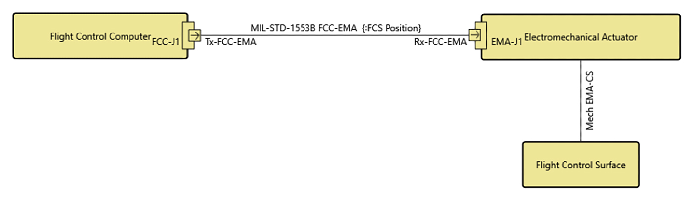
The wiring harness between the “Flight Control Computer” and “Electromechanical Actuator” is still modeled as a Link, named “MIL-STD-1553B FCC-EMA.” However, a jack connector, “FCC-J1,” and one out-pin, “TX-FCC-EMA,” are also modeled for the flight control computer. Similarly, a jack connector, “EMA-J1,” and one in-pin, “Rx-FCC-EMA,” are modeled for the electromechanical actuator. Notice that the mechanical linkage between the actuator and the flight control surface is still a simple Link since there is no “pinout” for such interface.
This approach works well when engineers need visibility into connectors and pin mappings without requiring fullscale modeling of the cable’s structure or behavior. It enhances communication with electrical engineering teams and subcontractors while maintaining a reasonable level of modeling effort. The tradeoff is that the cable itself remains an abstract Link; physical properties and relationships to the broader system are still not represented.
Modeling the Wiring Harness as a Component
The most comprehensive method to model a wiring harness is to treat it as a Component. A wiring harness has a defined structure that can be decomposed such as an organized assembly of electrical wires, cables, and connector. It has behaviors such as transmitting electrical power and signals and Improving reliability, protect against environmental stress. A wiring harness is, in fact, a component (with a part number) of a system. The same flight control actuation subsystem in the previous method can be modeled as follows.
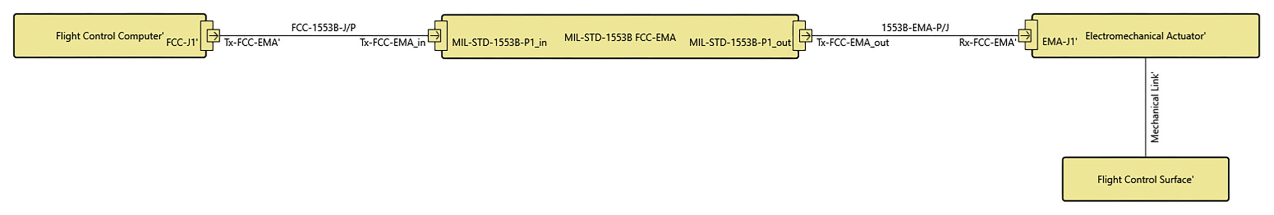
The Connectors and pins are still modeled as Ports. However, the MIL-STD-1553B cable is now represented by a Component. Links are still employed in this method, but to represent the abstract connection between the flight control computer and the 1553B cable and between the 1553B cable and the actuator. The cable can now have mass and dimensions. It can be decomposed to wires that also have mass and dimensions. The cable can also have modeled states and functions including (executable observables, process flow and control).
Let’s look at a typical function of a harness: bundling wires and providing structure.
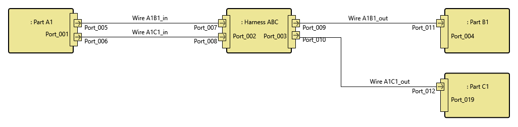
In this example, “Harness ABC” still connects “Part A1” to “Part B1” and “Part C1” as a Component and its links. But this setup also shows the harness as a single bundle of wires: “A1B1” and “A1C1” going from one source to two destinations. In the previous modeling method, a harness as a Link cannot be shown connecting one-to-many Components. Links are only one-to-one.
A Boeing 747 is believed to have 150 miles of wiring which weighs in the range of several thousand pounds. If weight budget and distribution, dimensions, and other physical constraints of wiring harnesses are important to your organization, modeling them as Components is an advantage. This modeling method is also a good option to understand the behaviors of wiring harnesses, e.g., support and thermal expansion/contraction functions. While this approach provides the highest fidelity, it increases modeling time, complexity, and the likelihood of errors.
Conclusion
Selecting an appropriate strategy for modeling wiring harnesses in GENESYS depends on the fidelity required to support engineering decisionmaking. At a high system-level, representing harnesses as simple Links provides an efficient abstraction when detailed physical or behavioral attributes are unnecessary. Introducing connectors and pinouts with Ports increases interface clarity and supports electrical engineering workflows while maintaining manageable model complexity. When higherresolution insight is needed such as mass properties, cable decomposition, or behavioral modeling, capturing the harness as a full Component enables detailed physical and functional characterization. This added rigor, however, increases modeling cost, verification effort, and overall project complexity. Engineers should select the modeling approach that delivers the level of precision required by stakeholders without burdening the architecture model with unnecessary detail.
Author’s note: The author would like to thank Geoffrey NG, Technical Marketing Manager at Zuken, for his technical contribution and review of this blog.


