


Last month, we explored Vitech’s CSDL, providing an overview of the modeling language and a hypothetical pathway for constructing a system. We reinforced these concepts with a real-world example, though limited to a few levels of decomposition.
Over the past two weeks, we shifted focus to Vitech’s STRATA methodology, demonstrating how it ensures models, regardless of the modeling language, remain concise, consistent, clear, and correct through multiple layers of decomposition.
This week, we take STRATA from theory to practice. Using a real-world scenario, we’ll show how this methodology provides structured guidance for navigating layers and building connected elements across all pillars of MBSE with confidence. We’ll take advantage of STRATA’s ability to let us model what we know, regardless of where it fits into the STRATA logic map and then use GENESYS’ built-in completeness and integrity checker rules to ensure that the overall model that we form is complete and consistent.
Our case study: a water treatment system, which is an essential component of large-scale civil infrastructure. Just as a cardiac pacemaker safeguards a single life, a water treatment facility safeguards the health and vitality of an entire community or region.
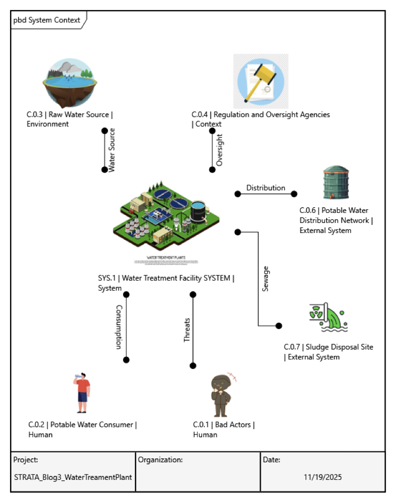
SYSTEM CONTEXT
Establishing the system context is essential for bounding and understanding the problem. It defines the system within its intended environment and identifies external interfaces that supply critical inputs or consume outputs. Without this big-picture view, validating whether the system meets its intended needs becomes nearly impossible.
For this case study, we’ll keep the scope lighter than a full system-of-systems approach while highlighting key interfaces to set the tone for STRATA:
- External System Interfaces: Raw Water Source, Potable Water Distribution Network, Sludge Disposal Site
- External User Interfaces: End Consumers, Bad Actors
- External Support Interfaces: Regulatory Oversight
- System Segments (in the System of Design control volume): Potable Water Storage Tank, Monitoring System, Operations and Maintenance Staff
With these in place, we begin at the L0 Context System physical architecture, forming the foundation for our problem statement and illustrating it with a Physical Block Diagram and STRATA logic map.
From this point, STRATA provides multiple paths forward. Some may choose to refine the physical architecture through component decomposition, while others may begin modeling the functional architecture based on known system behaviors. For this example, we’ll advance by capturing requirements derived from user needs and stakeholder expectations. The key is to ensure every new element originates from the existing model, maintaining relationships, traceability, and proper inheritance.
USER NEEDS TO REQUIREMENTS AND VERIFICATION PLANNING
Requirements can stem from many sources: customer needs, business objectives, environmental constraints, and more. Here, however, we’ll elicit requirements from use cases established within our system context architecture. This direct linkage ensures consistency by design.
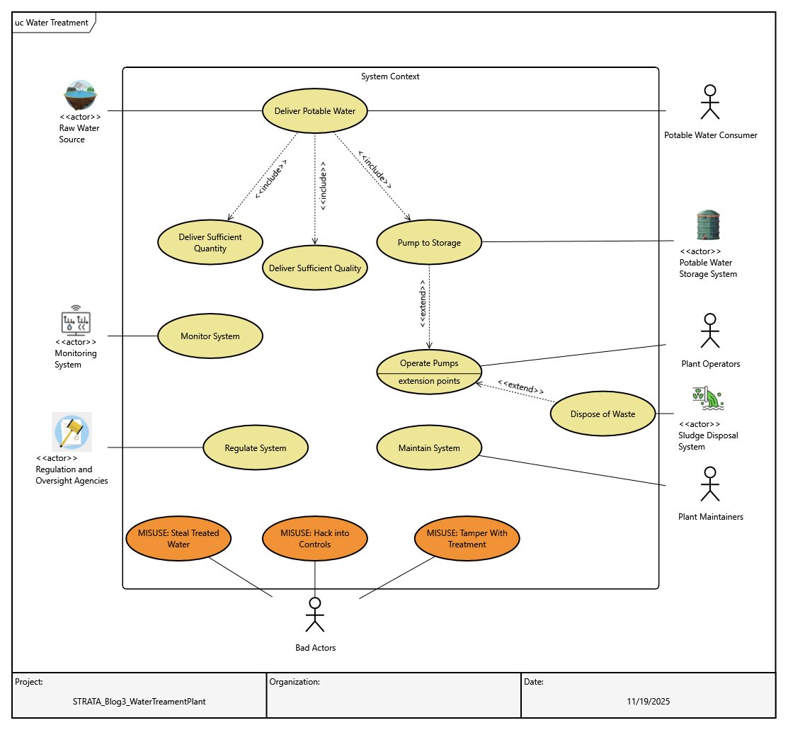
We’ve mapped all physical elements in the system context and identified use cases they may support. From these use cases, we can derive high-level requirements based on known information or reasonable assumptions. Below is a requirements diagram in familiar SysML format, created in GENESYS, illustrating the originating requirements elicited from these modeled use cases.
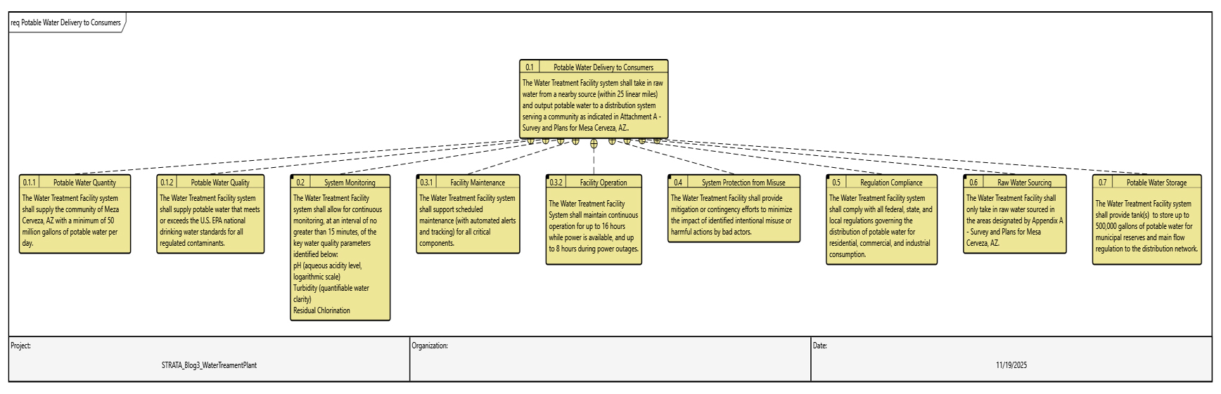
Establishing a complete set of requirements and a corresponding verification plan provides the modeler with confidence that every design decision is traceable, every function is validated, and the system can be proven to meet its intended purpose. This foundation reduces risk, supports compliance, and accelerates progress toward a robust, integrated architecture.
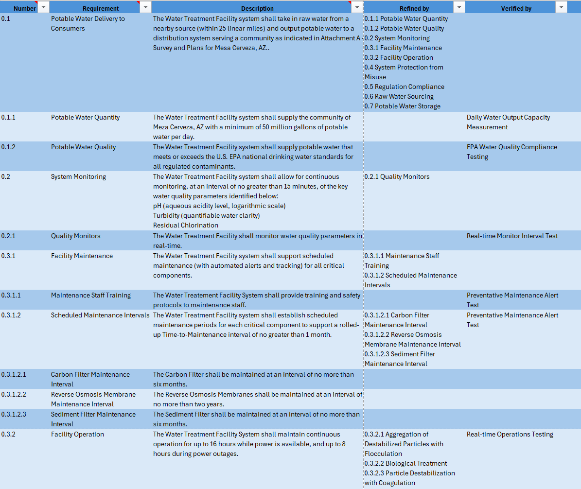
*Visualization above is a subset of the full requirements traceability table
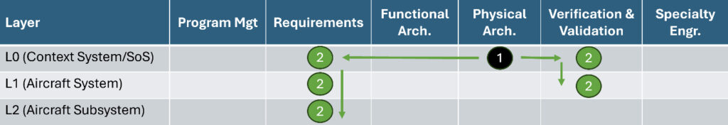
REQUIREMENTS TO FUNCTIONAL ANALYSIS
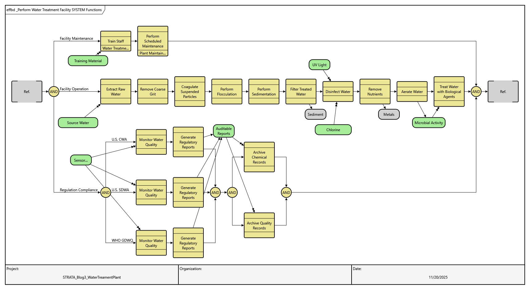
We now have requirements defined at both the system and subsystem levels for our Water Treatment Facility, along with high-level verification planning with everything tied back to the needs established through use cases. Some of these requirements are functional in nature, making functional analysis essential to capture known behaviors and ensure they integrate into a complete, coherent architecture. This process also strengthens traceability by ensuring every function and requirement is linked to its origin, supporting validation and compliance throughout the design lifecycle. Below are examples of functions we can analyze and decompose.
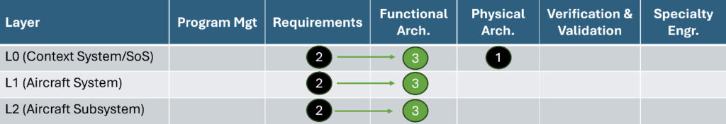
PERFORMING GAP ANALYSIS AND INTRODUCING PHYSICAL ARCHITECTURE
We’re now deep into the behavioral architecture: the “what the system does” for the Water Treatment Facility, derived from what we know. At this stage, we can use our tool to perform a gap analysis to identify missing elements needed to complete a functional and physical view of the architecture. A matrix can be constructed to perform a pairwise analysis to determine what modeled functions do not have a modeled component to perform it. This analysis can be extended with additional matrices to confirm that every requirement is represented somewhere in the architecture and that each has an associated verification plan. Notably, a spider diagram can be used to show all of the same information in one picture, though this view would almost always be too dense to present in a blog format. We’ll narrow our focus to the functional gap analysis in the matrix shown below. Any missing relation arrows reveal that we need another element in our physical architecture to perform the associated function.
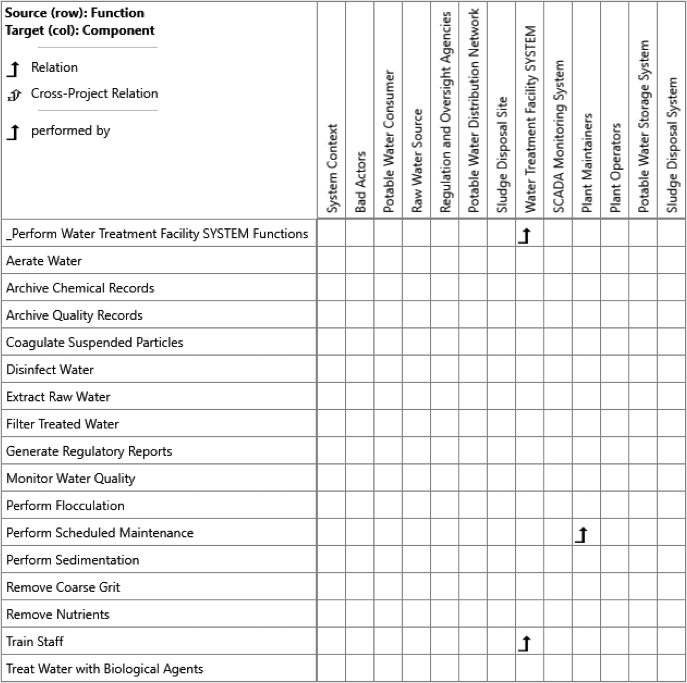
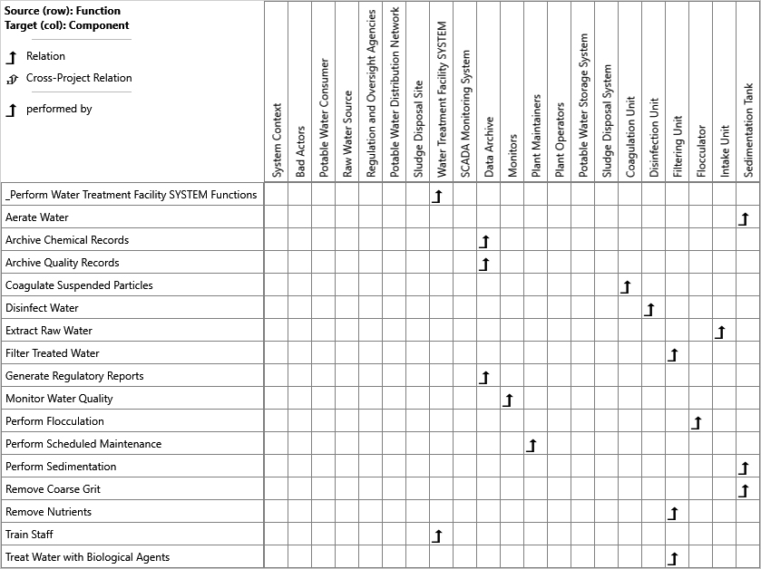
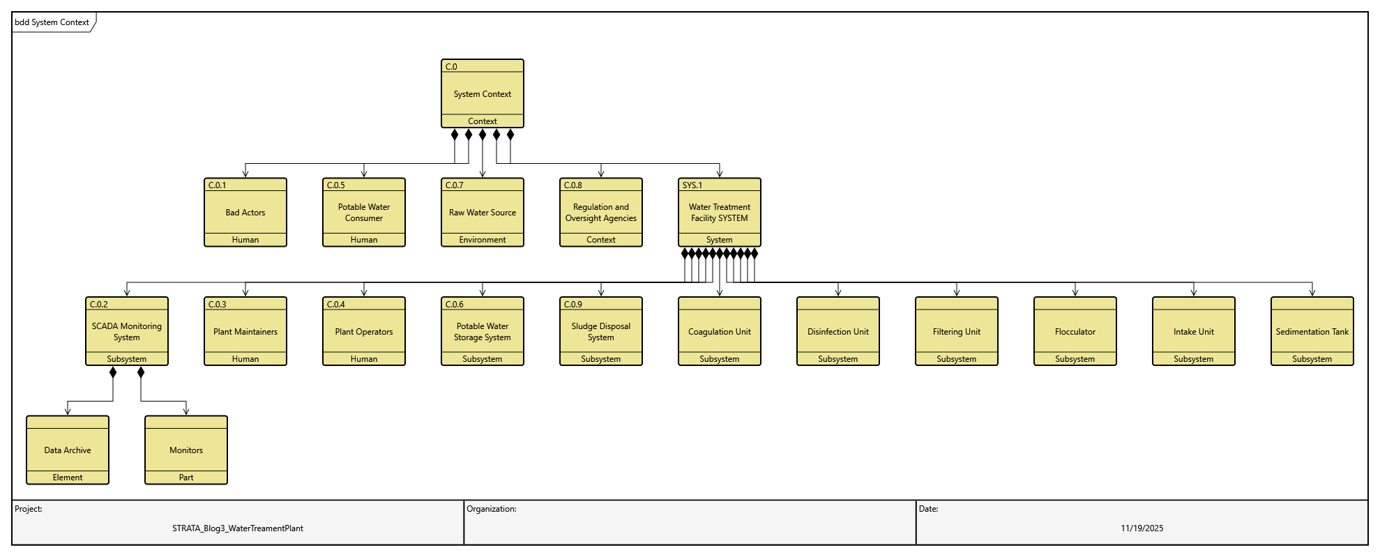
We will add appropriate components to fill these gaps. These components need not represent the final architecture but serve as a strong starting point for answering the question: “What is our system?” We’ll first illustrate these gaps being filled in an updated matrix, followed by a Block Definition Diagram presenting the notional physical hierarchy.
THE PATH FORWARD…?
Where do we go from here? The roadmap provided by STRATA lights the way. If we have knowledge of deeper layers, we can follow those relationships and connect them to the rest of the model. If programmatic or specialty engineering pillars need attention within the layers we’ve defined, that can be the next step. We can also expand verification planning as more information becomes available. The key is to keep modeling what we know and avoid getting stuck in any single layer. Progress continues until the modeling purpose is fulfilled.
CONCLUSION
As we’ve seen throughout this case study, applying STRATA transforms modeling from a collection of disconnected artifacts into a structured, traceable architecture. By starting with system context, progressing through requirements, and integrating functional and physical views, we create a model that is not only comprehensive but also actionable. Each step builds on what we know, ensuring clarity, completeness, correctness, and consistency: the four pillars that underpin successful MBSE.
This approach is more than a workflow; it’s a safeguard against ambiguity and fragmentation. STRATA provides the roadmap to keep models coherent across layers, enabling confident decision-making and reducing risk. Whether you’re designing a pacemaker for one life or a water treatment facility for an entire community, the principle remains the same: a disciplined methodology is essential for delivering systems that meet their intended purpose with precision and reliability.


