

I have received many questions lately about managing multiple operational architectures in a single project. Frequently, this question is asked in the context of documenting the current as well as the future state of the architecture. In this article, I will discuss the steps in documenting an As-Is (or current) Architecture and a To-Be (or future) Architecture in the same project.
The starting point for this discussion is opening a project using the Operational Architecture Schema. The key elements and relations that are used to define an operational architecture are shown in the following diagram.
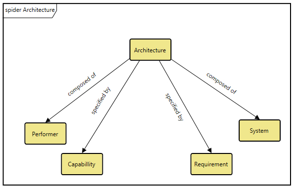
Figure 1 – Basic Relations to an Architecture Entity
An Architecture entity in the model has the attribute named “Time Frame.” This attribute, which identifies where the Architecture falls along the development path, uses an enumerated list with the following choices: As-Is, Objective, Threshold, To-Be, Transitional. The list of time frames is provided as an initial set of time frame characteristics for Architecture phases; other choices can be added by modifying the schema to expand this list.
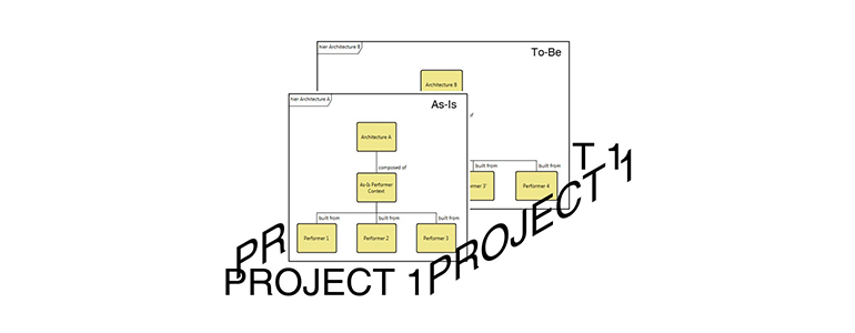
For the sake of illustration, I will assume an As-Is Architecture (named: “Architecture A”) and a To-Be Architecture (named: “Architecture B”) which are documented in one project. For Architecture A, the Time Frame attribute is set to “As-Is” by selecting that choice from the list. In a similar fashion, the “Time Frame” attribute is set to “To-Be” for Architecture B. The project now contains two Architecture entities placed separately in time.
In the As-Is Architecture, we have a set of Performers and Capabilities as shown in the following two diagrams:
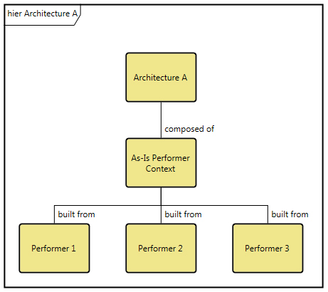
Figure 2 – Performers Supporting the As-Is Architecture
The As-Is Architecture provides the Capabilities as provided in the following diagram:
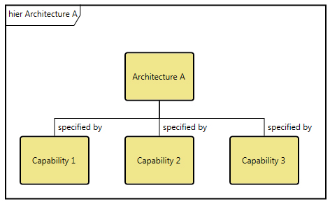
Figure 3 – Capabilities Provided in the As-Is Architecture
Moving to the other operational architecture, the To-Be Architecture (named: “Architecture B”), we will have a modified set of Performers. In this case, Architecture B, the “To-Be” architecture, has an additional Performer, Performer 4. This modified architecture can be shown in a diagram similar to Figure 2, but starting with the To-Be Architecture instead of Figure 2’s “As-Is” element. In the new diagram, some of the Performers in the As-Is Architecture may remain, some Performers may be modified, and new Performers may be added. Figure 4 provides a representation of the future Performer architecture for the “To-Be” architecture entity.
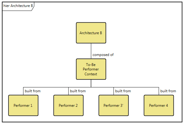
Figure 4 – Future Architecture Performer Configuration
Similar to the Performer architecture, a unique set of Capabilities can be identified in the To-Be architecture. Here again, some of the current capabilities are maintained in the To-Be architecture, some are removed, and new capabilities are added to the To-Be architecture. These modifications are shown in the following diagram.
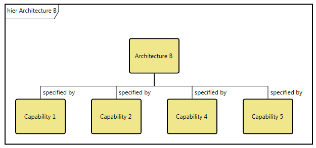
Figure 5 – Future Architecture Capabilities
We can extend this concept to also reflect interim or transitional architectures as steps toward the endpoint To-Be Architecture with modifications allocated to each step. These are created using the “Time Frame” attribute set to define the place in time for each step. The key to this discussion is the ability to manage and document even a succession of As-Is and To-Be architectures in one project model in CORE or GENESYS.
It really is that easy!


