


NOTE: This is the first of two blogs illustrating how the CSDL can help construct a fairly detailed descriptive system model that connects the physical and behavioral architecture quicker than you might think and all traced back to requirements. Part 1 will move from requirements to developing the start of a physical architecture with rudimentary interface definition. That will provide a bridge to begin to develop the behavioral architecture through functional flows and culminate in functional allocation to “close the loop”, and that will be covered next week.
We have introduced you to Vitech’s CSDL and suggested how this language can enhance the value proposition of descriptive architecture modeling by expanding on what SysML v.1 has provided. In the previous blogs, we suggested CSDL provides an easier, more intuitive way to start modeling a system that can enable teams to start modeling quicker, illuminate pathways for model refinement, and communicate a tailored set of important engineering data that can be absorbed and considered by a wide array of stakeholders.
Today, we’ll dispense with the theoretical and the hypothetical and show how CSDL can be applied to a real-world systems engineering problem, at least at a high-level.
The system of interest is a high-level architecture of a leadless cardiac pacemaker – one of the more ubiquitous products coming out of the medical devices industry, evolving over decades of innovation, that nearly everyone should be familiar with.
By using the concepts of the CSDL applied through Vitech’s GENESYS MBSE tool we can begin to see the power of the natural modeling language to get to an appreciable depth relatively quickly.
SYSTEM CONTEXT
One of the better places to start describing a system is at the contextual level – that is, the system of interest (our pacemaker) operating within a defined environment and interacting with other external systems. The view below shows the highest level of how the designed system will solve the big picture problem.
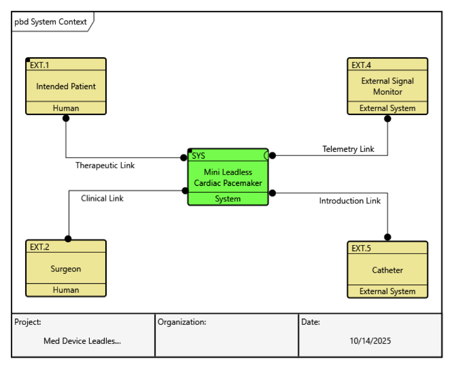
This is a simple physical block diagram that shows our leadless cardiac pacemaker interacting with two external systems (the introduction catheter and a signal monitor for remote sensing), and two human “systems” (the patient and the surgeon). The CSDL avoids esoteric typing and usage nomenclature by describing all of these interacting elements as Components without any loss of meaning at this level of abstraction – they are all treated and can be related to other elements the same. The differences lie in the attributes that can be assigned to these components. Moreover, their implied interaction with one another is easily understood by simple statements that need not be decoded: the “Mini Leadless Cardiac Pacemaker” is connected to the “Catheter” via the Introduction Link; the “Mini Leadless Cardiac Pacemaker” is connected to “Patient” via the Therapeutic Link, and so on. These names worked for us to describe the system context, and you may use different terms – but the environment is pretty well understood so far, at least at this level.
DESCRIBING THE SYSTEM
There is no one way to begin modeling a descriptive system that works best in all applications, but no matter where you start, by using following the logic embedded in the CSDL meta-model, we can describe and communicate the physical and behavioral architecture of this device pretty quickly.This then provides the foundation for model refinement and connect all of the relevant data.
SYSTEM REQUIREMENTS
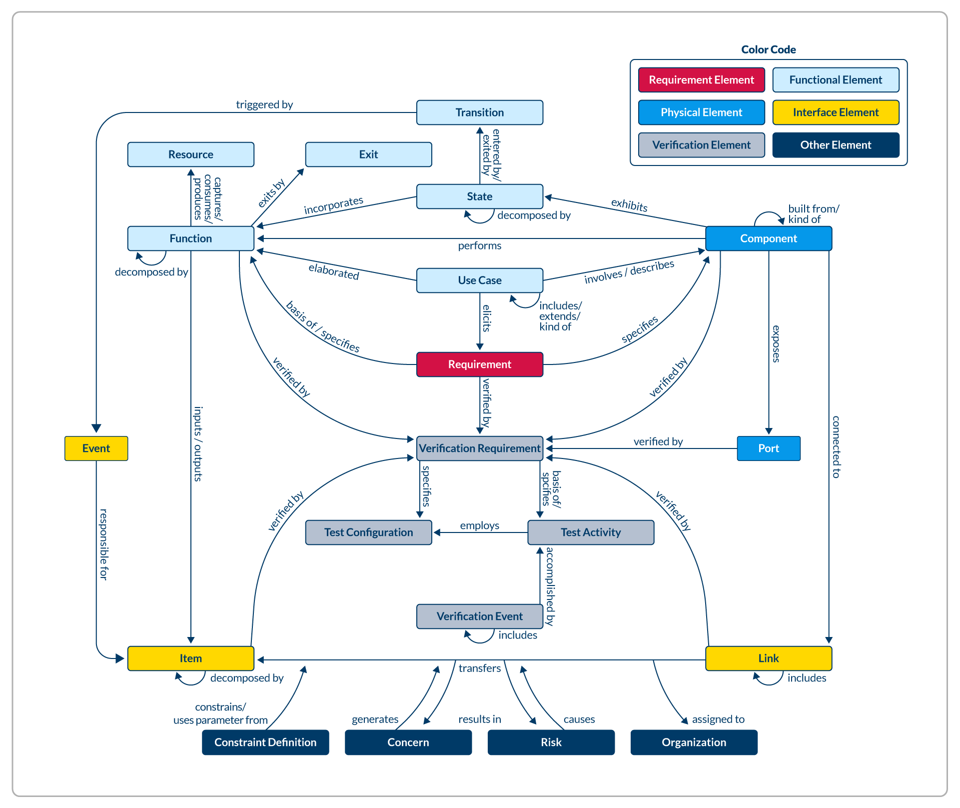
Whether they are created and maintained wholly in the tool, or imported from and managed elsewhere, the center of the systems engineer’s universe is often found within the system requirements – for better or for worse. It’s no surprise that the Requirements class is found in the middle of the essential CSDL meta-model representation. It’s not a terrible place to start if high-level requirements are known or conceivable before modeling.
GENESYS can display requirements in a very familiar and digestible tabular format, which can now provide our starting point to flesh out our descriptive architectures.
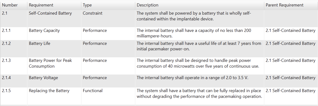
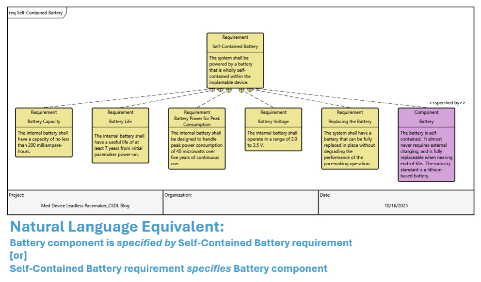
This subset of the system requirements set deals with how and how well the pacemaker is powered (by a self-contained battery). The requirements themselves are first order entities defined within a Class (Requirement, as shown in the meta-model), and is further defined with attributes and relationships with other entities in the model. Here, each requirement has been given a number (for easy indexing and navigation), a type, and a description which is usually the requirement text itself. In this table we can also see the beginnings of a hierarchical relationship for these requirements. At this point, the requirements numbered 2.1.1 through 2.1.5 are all children requirements related to the parent requirement: Self-Contained Battery. To put it plainly: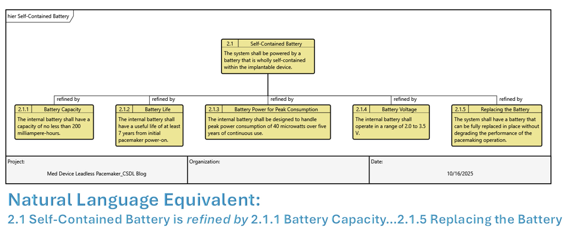
These requirements can be further refined and related to whatever hierarchical complexity is necessary to describe the system.
CREATING AND RELATING NECESSARY COMPONENTS
Note that Requirements 2.1 is typed as “constraint requirements” – that is, an imposed design feature that cannot be avoided. This requirement speaks to the unambiguous need of a battery wholly contained within the system that is replaceable. At a high level, this battery must exist in our design as an entity of the Class: Component (a piece of “what the system IS”). We create and relate this new component into our system model:
Clearly, this battery is a piece of the designed system that has many other pieces, so how do we describe how it fits in? The hierarchical relationship between components is the built from/built in relationship in CSDL. As we introduce more components into our model, we can relate them to one another and show as complete a physical hierarchy as is needed to describe our system.
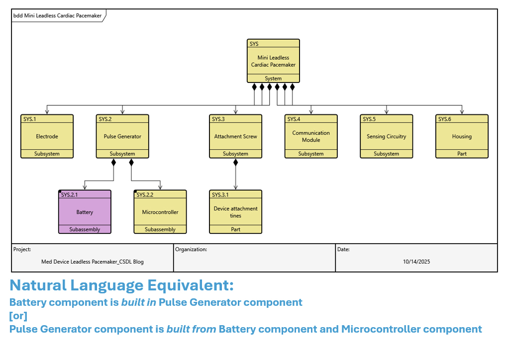
As this architecture description evolves, we can decide whether or not this hierarchy is an accurate representation of “what the system is” – the subsystems, subassemblies and parts – but we are well on our way of describing the physical architecture of this complex system within these three levels.
DESCRIBING THE PHYSICAL INTERFACES
We have already seen how we can begin to describe the interfaces between components in the System Context view previously. Now that we are deeper into our design, we can also show how we can construct the model of physical architecture to include a description of behavioral architecture. The CSDL relationship we will use again is the connected to relationship. Every component that is connected to the same entity within the Link class has a defined interface which can be further described and refined with attributes assigned to those links. As the meta-model shows, the links can also be decomposed hierarchically by way of the includes/included in relationship. At this point, we won’t need this to begin to specify our physical interfaces.
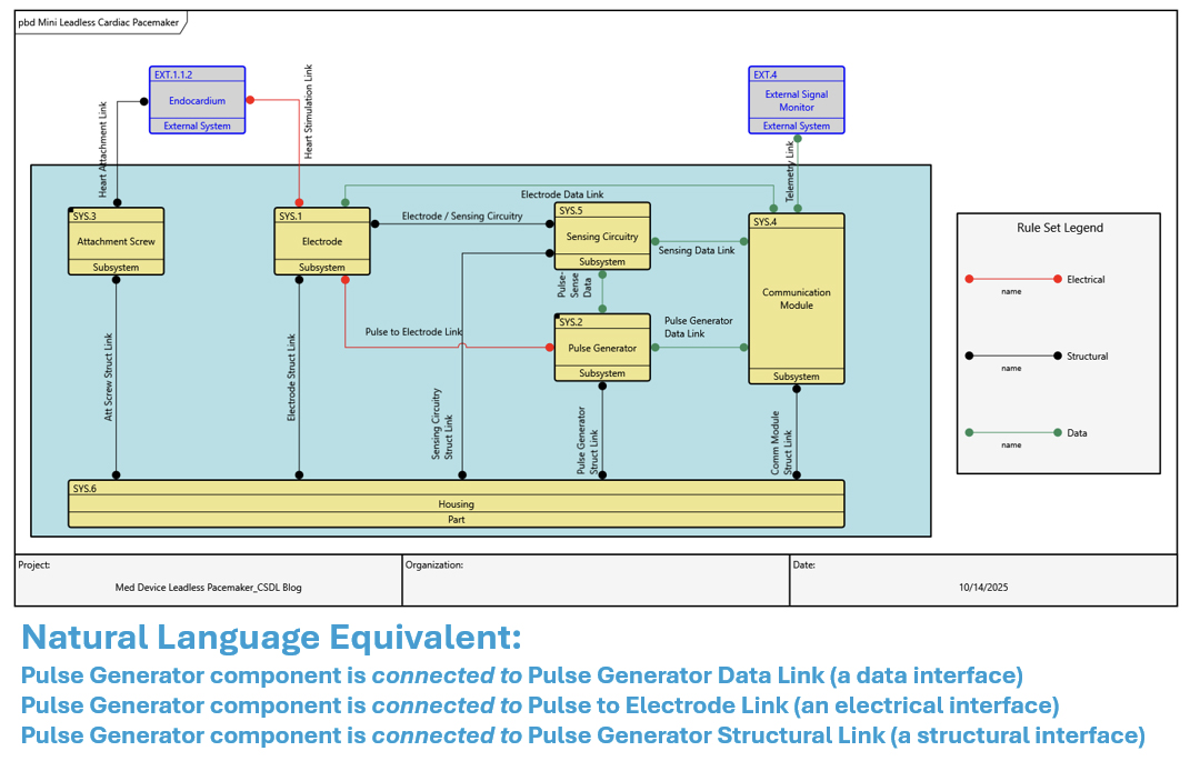
This Physical Block Diagram of our pacemaker system has a bit to unpack. Our “Battery” subassembly was built in our “Pulse Generator” subsystem, as we have defined our components. The “Pulse Generator” subsystem here is shown to have a data interface to the “Communication Module” subsystem, an electrical interface with the “Electrode” subsystem and a structural interface to the “Housing” part. All of this is established by each of these component entities being connected to the same Link entities.
In our next blog, we’ll add more detail to the interface and bridge the physical aspects of the system model to the system behavior through both item flow and functional allocation using the concepts in the CSDL. Stay tuned!


