

Modeling behavior in SysML can be painstaking and difficult to communicate to a broad range of stakeholders. Fortunately, GENESYS makes it easy to use SysML constructs in a way that facilitates a comprehensive and consistent behavioral model and makes it easier to discuss with a broad range of stakeholders.
What do we mean by the term behavior? Behavior describes the totality of what a system does, as opposed to how it is implemented. SysML defines many notions of behavior—two of which are activities and interactions. SysML defines activities as pieces of behavior that transform inputs into outputs. True to SysML’s software heritage, interactions are defined as an expression of behavior in a sequence of message exchanges. GENESYS aligns both activities and interactions with the GENESYS class function, essentially defining a function as a piece of behavior that transforms inputs into outputs through a sequence of message exchanges.
Equating these two major notions of SysML behavior—activities and interactions—with the single notion of a function helps to unify the modeling of behavior and avoids the necessity of aligning activities with interactions across diagram types. In this month’s blog, I’ll briefly describe how behavior is modeled in GENESYS with activities.
In SysML, activities may be represented on BDDs just as blocks. However, in GENESYS, you will notice that it is not possible to view your functions with a Block Definition Diagram (BDD). As I explained in my June blogs (Modeling SysML Blocks in GENESYS: Part I and Modeling SysML Blocks in GENESYS: Part II), in GENESYS, SysML blocks are strictly aligned with the GENESYS class component, so the BDD is reserved for displaying components only. This avoids confusing stakeholders when a BDD is used to display blocks that do not represent the structure of the system design, or when used to define reference associations between activities and blocks.
GENESYS does allow you to view a functional hierarchy (as well as a component hierarchy and other class hierarchies) with the hierarchy diagram as depicted in Figure 1. Note that Function X decomposes into functions x.1, x.2, and x.3. In GENESYS, you can alter the content of a hierarchy diagram by changing the node template to display desired information.
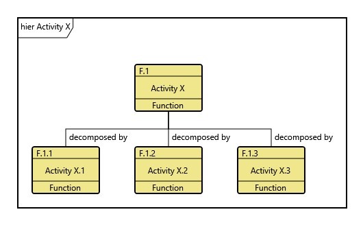
Figure 1. A Functional Hierarchy
Activity diagrams are used in SysML to describe the behavior of an activity. SysML introduces the notion of an action when depicting behavior on an activity diagram. Actions are modeled as instances of an activity’s direct decomposition. In GENESYS, the notion of actions is avoided for the sake of simplicity, so when you look at an activity diagram in GENESYS you are looking at the direct decomposition of that activity into a flow of subordinate activities. SysML also defines several different categories of actions: invocation actions, call behavior actions, receive actions, send actions. Just as with activities, GENESYS aligns the notion of actions with their activities, and hence with the class function. All categories of actions and their associated activities can be expressed using an appropriate function as the keeper for the necessary behavior. Functions are then related directly with other functions with the “decomposed by/ decomposes” relationships to form a functional hierarchy and functional decomposition.
For example, as depicted in the activity diagram in Figure 2, we see the children of Activity X depicted in Figure 1 now appear on the activity diagram for Activities X as shown in Figure 2, without the overloaded notation for actions.
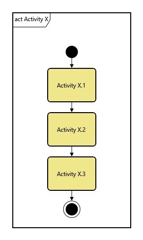
Figure 2. Activity Diagram
With activity diagrams, you can display the logical flow of intended behavior. Using fork, join, and merge nodes, as well as looping, or iterative constructs, you can model behavioral logic as depicted in Figure 3. Join nodes in GENESYS have one join specification: all branches must complete before the functional flow is allowed to proceed. You can effectively create other join specifications by using a combination of fork and join nodes to model behavior occurring in parallel. You can use merge nodes to create exclusive OR logic. You can also indicate which branch or branches are allowed to end the parallel behavior and proceed with the logical flow.
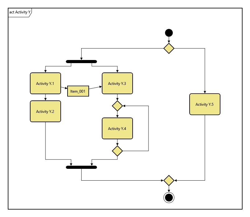
Figure 3. Activity flow with fork, join, and looping
Simulation of Behavior
GENESYS is designed to model with discrete-events rather than on petri-net tokens. Discrete-event modeling is a more generalized (less software-centric) behavioral modeling technique that allows for a more detailed functional model of system behavior, and allows for a more detailed study of system performance through discrete-event simulation. Engineers create functions to model the behavior embedded in petri-net constructs. Using functions to describe behavior allows you to model the token flow behavior directly, resulting in a more complete and concise representation of systems behavior. Discrete-event models also have the additional benefit of being comprehensible to a wide range of system stakeholders. Having a more detailed and validated behavioral model in turn results in a more complete requirements specification.
Inputs and outputs of functions in the form of data, matter or energy are aligned with the GENESYS class item. Items can also act as triggers and fill the purpose of parameters, signals, or call events in SysML. Discrete-events are generated when functions begin and end as governed by logical constructs and by triggering items that affect the flow. Durations of functions can be set to constants, or taken from a probability distribution. Also, detailed behavior of a function, called opaque or function behavior in SysML, can be modeled in GENESYS using scripts. Note that streaming flows can be modeled with appropriate functionality that will continually generate item flows through the model. Lastly, the discrete-event simulation can be configured to account for structural parameters of a component that would affect performance such as processing rate or bandwidth.
Activities and interactions are two of the SysML concepts for modeling system behavior. SysML also defines concepts for flow of data, energy, or matter. SysML defines concepts such as parameters, signals, items, flows, or messages to model behavior inputs and outputs.
GENESYS combines the two notions of behavior into the GENESYS class function, and combines the many notions of input and output into a single notion of an item. Streamlining the modeling of behavior allows you to create simpler and more consistent models of behavior without any loss of fidelity, and allows you to better communicate system behavior to stakeholders. In the end, it helps you to define a more complete set of requirements specifications for your system.
If you have any questions about activities and SysML in general, feel free to contact me at mark.simons@vitechcorp.com. Remember, too, that I’m available as part of your CORE or GENESYS maintenance agreement to help explain the systems engineering uses of Vitech tools.


