

All too often we think of systems engineering as a technique that is used to perform just the initial design of a system. We don’t appreciate the value of a system in later stages of the product lifecycle except as a means to inform the design of the replacement system. To make matters worse, model-based systems engineering (MBSE) is usually positioned as providing support only to the concept development and system design phases of the lifecycle. We don’t explain how the system design information contained in the model can facilitate our responsibilities as system engineers in later lifecycle stages.
In this article, I will explain how system design information in the model can be used to help us evaluate and choose components when we either need to add a new supplier to our product, or we are looking to provide replacements for obsolescent parts.
The Challenge
Let’s look at an example situation. Assume that we completed a system design two years ago and from that design we selected a product made by ACME Engineering to meet the requirements of a particular configuration item. ACME Engineering has advised us that the product we have been using has been phased out of production and there is an updated model they suggest for a replacement.
We need to ensure that the replacement product can be used in our existing design without degrading overall system performance. How can we address this problem using the system design model?
We need to look at the requirements and functionality of the original design. Then we should look at how we tested the original design to verify the performance of the replacement product.
We have the specification document from the original system model which gives us the requirements used in the component design. We also need to identify the functions that the component performs, the items that those individual functions use, and the interfaces used to transfer the items between entities in the design.
All this is possible when the existing design was done using a robust design methodology and tool by creating a design model that remains accessible to us as we consider the feasibility of our replacement options. Without such a model, that analysis is problematic at best and might even require a complete redesign to consider replacement options.
The Answer
In our solution, we have a custom hierarchy entitled “Functional Impact of a Physical Change.” This hierarchy provides the functions and items (through “input,” “output,” and “triggered by” relations). The formal definition for this hierarchy diagram is shown in the figure below:
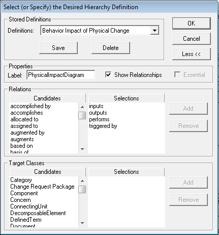
Figure 1. Behavior Impact of Physical Change
But how do we find the interfaces used by the component? We can also trace from the COMPONENT to the associated INTERFACE and LINK by creating a custom hierarchy as defined below:
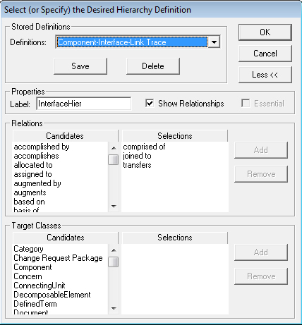
Figure 2. Traceability to Interfaces and Links
Selecting a component and using this hierarchy provides the following diagram:
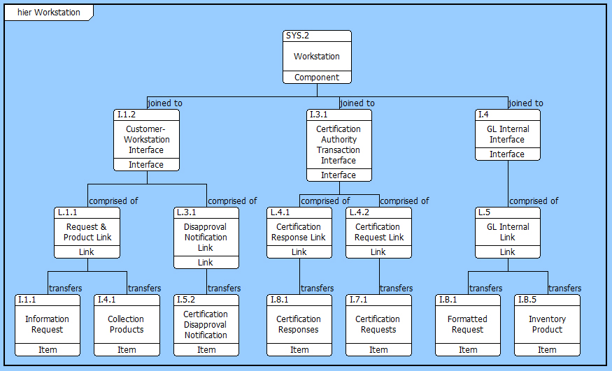
Figure 3. Workstation Interface and Link Traceability
Up to this point, we have traced through the legacy model, and determined the functions, requirements, and interfaces defined for the legacy component. We can use this information to do an engineering assessment of the proposed new product to determine, based on the design information, if the new component will be able to meet the desired performance.
Before we approve the use of the new product in the system, we need to test the product and verify that it will deliver the required performance. To determine the tests we need to perform, we can use the legacy MBSE model’s Verification Requirements and Verification Events used to verify the original product. Here again, the relations in the model are used to provide traceability, and we can do that in a new custom hierarchy diagram to get the following.
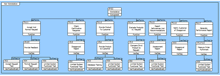
Figure 4. Traceability to Verification Events
This traceability provides the list of Verification Events that we will need to repeat in order to verify the new product. Using the list of Verification Events, we can also trace to the Test Procedures and Test Configurations used in the original component verification by utilizing the Verification Event hierarchy diagram. An example of this diagram for the Limited System Functional Test is provided below.
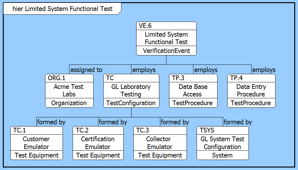
Figure 5. Verification Event and Traceability
Conclusion
Certifying a replacement product in the system architecture—several years following the original system design—seemed to be an extremely difficult problem to solve. However, the original MBSE system design, completed early in the system lifecycle, provided essential information. The original model supported the replacement analysis by providing the ability to trace through the model, revealing detailed information about the requirements, functions, and interface architecture that the replacement product has to meet. This traceability was extended to discover how the original component was verified and qualified, and we were able to easily identify needed test procedures and test configurations. The existence of the robust original model facilitated the replacement process, assuring a seamless transition without loss of functionality.


