MBSE and GENESYS alone cannot help you make the right design decision in a trade study. But the descriptive architecture in GENESYS can surely point the detailed designs in the right direction.
In Part One of this trade study discussion, we established some parameters for the motorcycle components to be evaluated. We will no go into how they can be useful in keeping the trades fair and consistent. If our descriptive architecture is doing a great job so far to help evaluate the point-and-shoot vs. corner-speed options qualitatively, the introduction of the Constraint Solver will add the quantitative aspect to our evaluation.
When we recall the goal of the Grand Prix motorcycle design, and of this trade study in particular, it is all about achieving the quickest time to enter, complete, and exit a turn on the race track. We have determined that two component parameters contribute to the ability to reach this goal. Together, the combination of these two parameters decides what kind of motorcycle (and riding strategy) will win the trade study. Suppose we have a way to calculate the total time it takes for each motorcycle design to attack a turn:
- For a typical point-and-shoot motorcycle:
vTimeCornerStab = (1 – vLongStiff) * 1.63 + 200 / vMaxPwr * 1.46
vTimeCornerStab is the total time where chassis stability and engine max power are the sensible winning combination.
vLongStiff is the chassis longitudinal stiffness defined in Part One. vLongStiff range is between 0 and 1, with 1 being the most rigid design value.
vMaxPwr is the engine max power output also defined in Part One. vMaxPwr range is equal to or greater than 200 hp.
In a real trade study, the (fictitious in this example) mathematical expression would have originated from historical and empirical evaluations of past point-and-shoot designs. This is why we stress that MBSE alone cannot give you all the tools necessary for a trade study. In this case, data engineering and applied mathematics are also essential.
- For a typical corner-speed motorcycle:
vTimeCornerFlex = 1 / (1 – vLongStiff) * 1.63 + 200 / vMaxPwr * 1.46
vTimeCornerFlex is the total time where chassis flexibility is the key.
vLongStiff is the chassis longitudinal stiffness defined in Part One. vLongStiff range is between -1 and 0, with -1 being the most flexible design value.
vMaxPwr is the engine max power output also defined in Part One. vMaxPwr range is equal to or less than 200 hp. Historically, we could not fit a more powerful engine into this type of chassis.
Again, the real-life mathematical expression would originate from historical and empirical evaluations of past corner-speed designs. We see that each physical component can place or remove a constraint upon another component. This is why a real-life trade study is more complex than just selecting the best available part technologies and mixing them into a system design that works.
Once we are confident with the mathematical expressions to be used in the trade study (total time to complete a turn in this case) we can model them in GENESYS as a Constraint Definition. More specifically, we will constrain the performance of the motorcycle functions to the characteristics of its selected components. To be perfectly clear, the mathematical expressions of a constraint definition do not automatically solve for the optimum parameters: chassis longitudinal stiffness and engine max power output. They are simply an attribute of a GENESYS class entity to help us quantitatively compare system’s performances when different combinations of parts are utilized.
Our constraint definition setup looks like this:
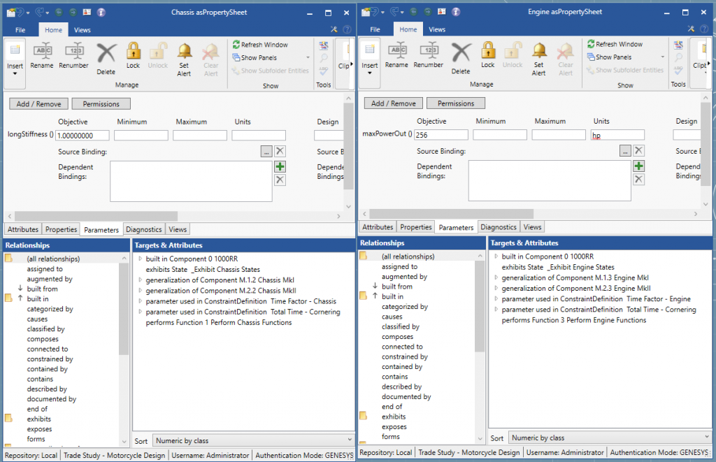
Standard practice is applied here when defining a constraint:
- Set the constrains target
- Identify the parameters used in the constraint definition
- Define dependent variables and independent variables
- Write the expression(s)
- Map the variables to the uses
The resulted parametric diagram looks like this:
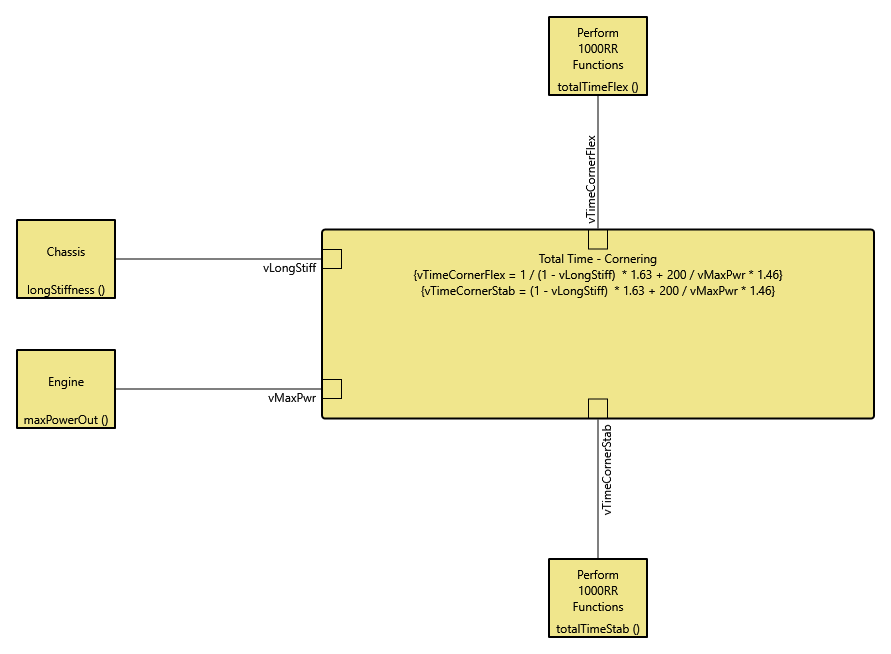
The objective values set for each of the parameters (longStiffness and maxPowerOut) will be used by the Constraint Solver to execute the expressions for vTimeCornerStab and vTimeCornerFlex. Let us try two sets of values, each representing the best-case scenario for each motorcycle design option.
The best possible point-and-shoot design with the best available chassis and engine:
- vLongStiff = 1
- vMaxPwr = 256 hp

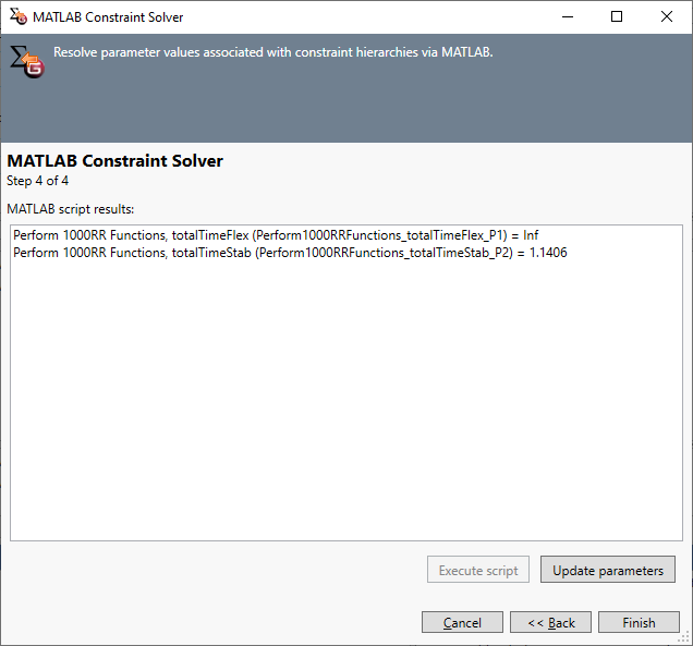
The constraint solver returns the results as:
- totalTimeFlex = Inf
- totalTimeStab = 1.1406 sec
Notice that the result for the corner-speed design is infinity. This is okay because one of the parameter values is outside of the expected range for this constraint definition. We do have the result for the best possible point-and-shoot design: 1.1406 seconds.
Similarly, with a corner-speed design, the best available chassis and engine:
- vLongStiff = -1
- vMaxPwr = 200 hp
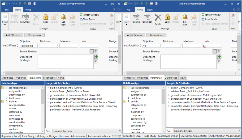
The constraint solver returns the results as:
- totalTimeFlex = 2.275 sec
- totalTimeStab = 4.720 sec
The result for the best possible corner-speed design is 2.275 sec. We can also observe that the result for the point-and-shoot design is way off (4.720 sec). This is okay because the parameter values used for this solver run are set for the corner-speed expression. They are out of range for the point-and-shoot expression. (In theory, we can split these two expressions into two separate constraint definitions and not worry about which result is valid with which valid inputs. I only chose to combine them into one constraint definition to reduce the number of diagrams for this discussion.)
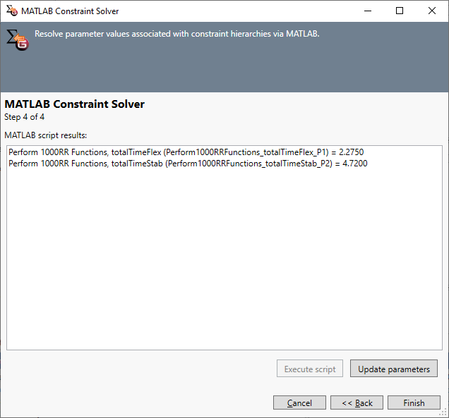
What does this finding tell us?
Given the component design availability for both design options, the best point-and-shoot design (1.1406 sec) beats the best corner-speed design (2.275 sec). As a manufacturer we might want to go with the point-and-shoot design if the Motorcycle’s turning performance is my most/only priority.
We can also identify where a design can be improved should component technology advances in the future. For example, if we run the solver again with vLongStiff = -1.5 (outside of the current corner-speed chassis technology), totalTimeFlex is then 2.112 seconds! 0.163 second is a huge improvement in MotoGP. So, should we as a manufacturer, really want to go with the corner-speed design to fit a particular rider’s style (Fabio Quartararo), we can accept the current limitations of component characteristics. Then, we will invest heavily in component R&D to improve the overall chassis design. GENESYS and MBSE allows us to make those informed decisions by exposing the interconnects between parts and interconnects between parts and the whole system.
“Cool light-weight calculations! I can do that in Excel or in MATLAB. Why do I need GENESYS for it?” one might ask. And it is a good question. The quantitative trade study can be done with a calculator. But, it would exist alone, incoherent without the qualitative understanding of how parts connect to make up a motorcycle system. This is where MBSE helps designers approach a solution holistically, and avoid the reductionist thinking of the Industrial Revolution age.
Another critical area where GENESYS can help a holistic trade study is modeling Behavior. Gluing different parts together is not the only way to create different systems. Understanding the behaviors of the parts and of the system is essential for a successful trade study. This is particularly apparent when software and electronics are involved in a complex system design. Though, the two motorcycle designs are greatly constrained by the components available to build them, each design can be further improved by manipulating its behaviors. After all, the whole is greater than the sum of its parts.
If we recall, the concept of inheritance is useful in leveraging the understanding of a physical baseline to explore two new physical architectures. Similarly, the concept of Threads and Integrated Behavior facilitates further developments of a known baselined behavior into two complex behavior architectures. The GENESYS schema relationship for this part of the trade study is reflects (or reflected in if going in the opposite direction):
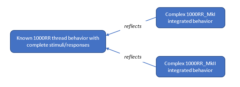
The baselined 1000RR motorcycle has a proven behavior with predictable stimuli and responses, and predictable functions performed by the chassis, electronics, engine, etc. The more complex and relatively unknown root functions of the MkI and MkII designs reflect the root function of the 1000RR baseline. The MkI and MkII component functions also reflect the 1000RR baselined component functions. Now, the team working on the MkI design can develop the best functions for a point-and-shoot motorcycle. The MkII team does the same thing for a corner-speed design. All the while, both teams can reference back to the baselined thread behavior, and in turn, to each other’s design. At the end of the process, both teams can compare and contrast the two functional architectures to one another, and to the known baseline. We can also apply a parametric analysis (as discussed earlier) to functions where appropriate.
At the beginning of this trade study discussion, I mentioned that the use of threads – integrated behavior was going to be a “variation” of the normal concept. This is because the typical threads – integrated behavior transition is done within the boundary of one system. In a trade study, there is more than one system being considered. Hence, a set of thread functions will need to converge to however-many integrated behavior architectures in the trade study:
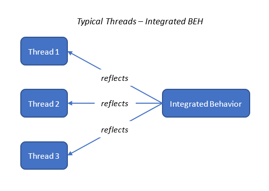
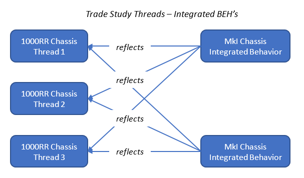
GENESYS is not the silver-bullet solution for a trade study (nor is any other single tool). A trade study is a monumental task jointly executed by many engineering disciplines with many different tools. This is where GENESYS and MBSE shines: being the connective tissue to bind all together. The descriptive architecture with the concepts of Physical Inheritance, Behavioral Reflection, and Constraint Definition facilitates traceability from a known baseline to the potential designs to be explored. This traceability through the GENESYS schema allows the trade study to be conducted consistently and fairly. And along the way, every design decision is made informedly and defensibly.


