


I’ve been building CORE and GENESYS models for quite a while now, and I’ve noticed a few common mistakes engineers new to modeling make, especially when it comes to the lack of using Exit Conditions and Exits. I’ve detected a reluctance in those new to modeling to use the exit conditions, instead trying to rely more on the select (OR) construct, and sometimes on parallel constructs combined with complicated triggering. While those constructs are really useful in the right situations, depicting a decision being made by a function is one of the most common operations you should be seeking to capture in your model. I sometimes get the feeling that engineers new to modeling are hesitant to use exits, that perhaps they don’t quite understand them fully. Let’s try and clear up any confusion on Exit Conditions and Exits and set the Exit record straight.
The most common mistake I see is the overuse of the select/OR construct. Those new to modeling tend to use this instead of modeling the Exits from the Function. Most engineers have been exposed to flow chart logic at some point in their education or experience. Perhaps, that’s why those inexperienced at modeling seem to gravitate towards them and overuse them. Seeing the diamond symbol in an Activity diagram is reassuring to the designer that is used to seeing the diamond symbol as the decision-making node in a flow chart. However, in a behavior model, the select/OR construct is really a probabilistic selection, meaning the decision on which branch of the construct is taken is solely based on probability. If you don’t specify the probabilities explicitly it will default to an equal division amongst the branches of the construct. While this may be ok in some rare cases, usually there is a reason to take one branch or another, not just pure chance. This is where Exit Conditions come in!
Functions take an input and create an output, that’s the simplest definition of a function. Our function is outputting a decision, it takes an input and decides to take one path or the other. These paths are Exit Conditions. Exit Conditions are made by relating the Exit entity (another class in the GENESYS database) with the function using the “exits by” relationship. GENESYS makes their use easy and provides in the Toolbox insert menu an Exit Condition icon that you can use to drag-drop onto the desired function to create the new exit easily.
Keep in mind that in order for the diagram to change you must insert more than one Exit Condition onto the function. Why is that? If you insert a single Exit Condition, you have effectively just named the default output of the function. Every function has an exit by default that allows the flow to continue. The addition of a second exit splits that flow. Since GENESYS is managing the structure of the model, it knows that since you’ve split the flow and it must recombine or join the flow. This is why GENESYS puts the OR/Diamond symbol at the place where both paths you just created come back together.
A key thing to remember is that the function can only take a single exit. The function must make choice so that the flow can continue along the chosen path. See the example below for both an EFFBD and an Activity Diagram:
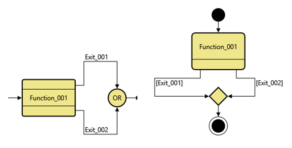
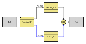
In these simple examples you can see how the multiple exit splits the flow into two paths and GENESYS automatically inserts the joining symbol (the OR/Diamond) that recombines the paths and allows the flow to continue. This logically makes a lot more sense for depicting a decision than a simple OR statement that looks like this:
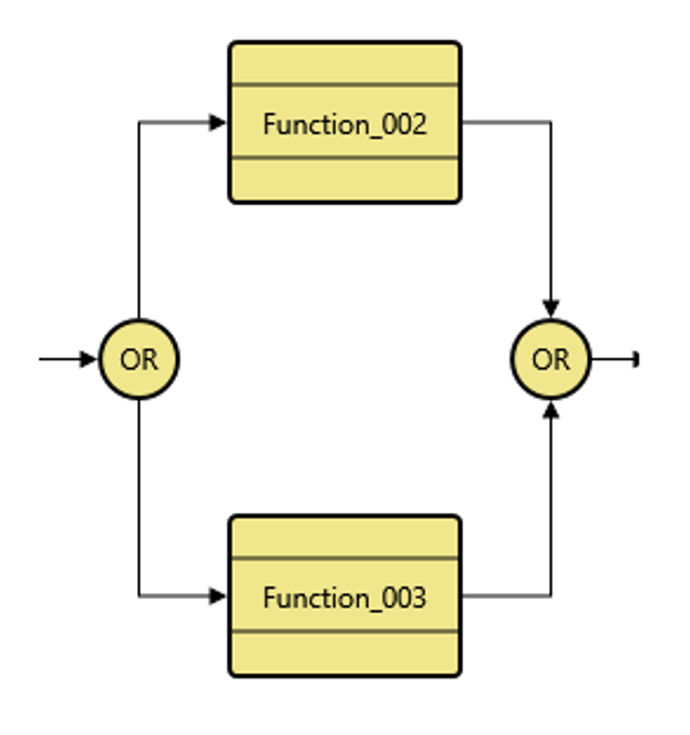
In this case, what’s making the decision to take one path or the other? The answer is just chance, just probability, not a decision being made by your system. I would like to point out a shortcoming in the standard flowchart and traditional SysML use of the Diamond to indicate a decision being made: what’s the allocation of that diamond? What system component is performing that decision function? In reality it is a function of the system making the decision, not just a decision being made out of thin air.
I do need to mention that in GENESYS by default the path the model will take through the Exit conditions of a function is based on probabilities, unless the user specifies a script to control the logic. GENESYS provides a powerful scripting language that allows the user to write code to govern the selection of an Exit Condition, but that’s an advanced topic, perhaps for a later post…The key here is to capture the exit logic.
Simply put, if you’re modeling any sort of complex behavior or process, you ought to be including Exit Conditions from your functions to capture the decisions being made by your functions. Capturing decision points is crucial to capturing and understanding the behavior of your system! Exit Conditions are simple to use and easy to understand once you get in the proper mindset.
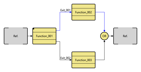
Let’s now move on to using the standalone Exit as a construct in our behavior diagrams. Using the Exit command from the insert menu in the Toolbox is analogous to a break statement in programming languages. When the standalone Exit is encountered it exits the flow entirely, moving the flow to the end of the diagram. This is most useful for dealing with decomposing behavior of a function that has Exit Conditions. In the diagram below, we have a simple function with two exit paths:
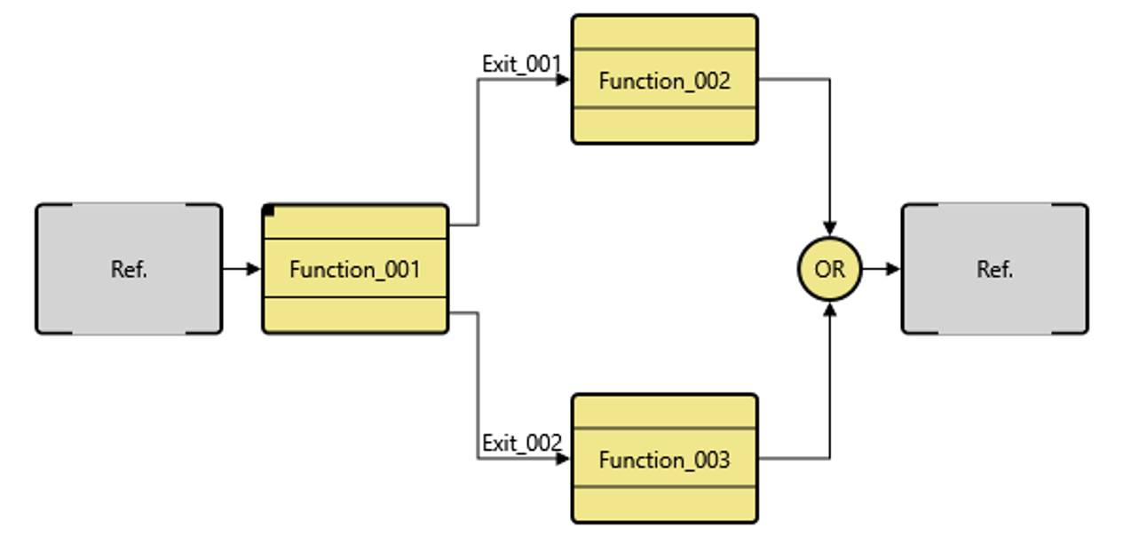
Note in this diagram the Ref. nodes are turned on. Reference nodes show the functions preceding the flow and after the flow we’re currently working with. You may have noticed the decomposition indicator in Function_001, indicating there is another level of behavior modeled in Function_001. How do we ensure that the logic below connects up to the exits at this level? This is where Exit’s come into play. In the decomposition of Function_001 we use the Exit constructs to match up to the exits at the parent level. In this next level diagram, we’ll see how this works.
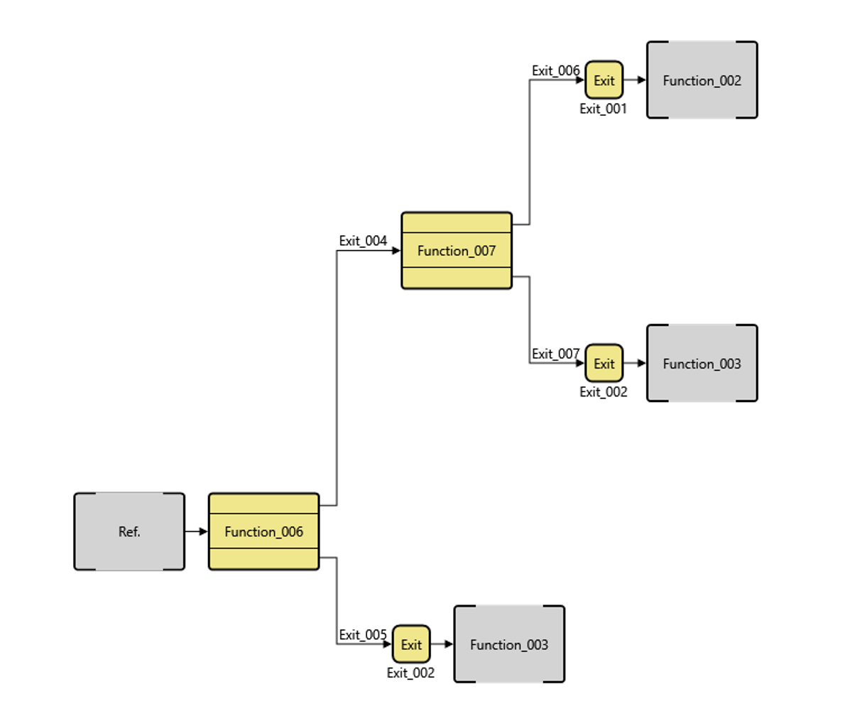
In this lower level diagram, we can see there are a couple of different decision functions that are driving the selection of higher-level Exit paths. The Exit constructs are used to connect this lower level of the model to the higher-level exit paths. As models become more complex using exits like this allow the design team to preserve the number and conditions for all the Exits as the model is decomposed. Note how the reference nodes now align to the higher-level functions.
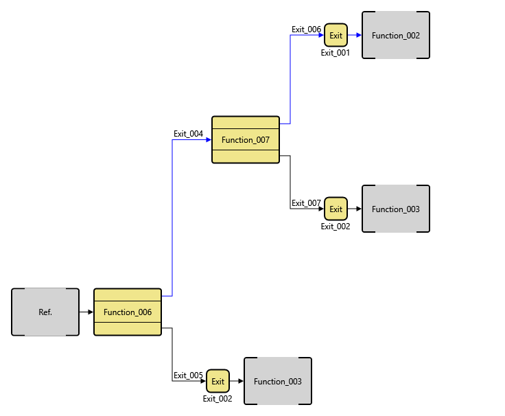
Let’s walk through the logic. If Function_006 takes Exit_005, then Exit_002 is returned at the higher level. The flow in this case is depicted by the blue line in the diagrams below:
The flow will lead to the Exit_002 path being taken and the execution of Function_003 in the higher-level flow as depicted here:
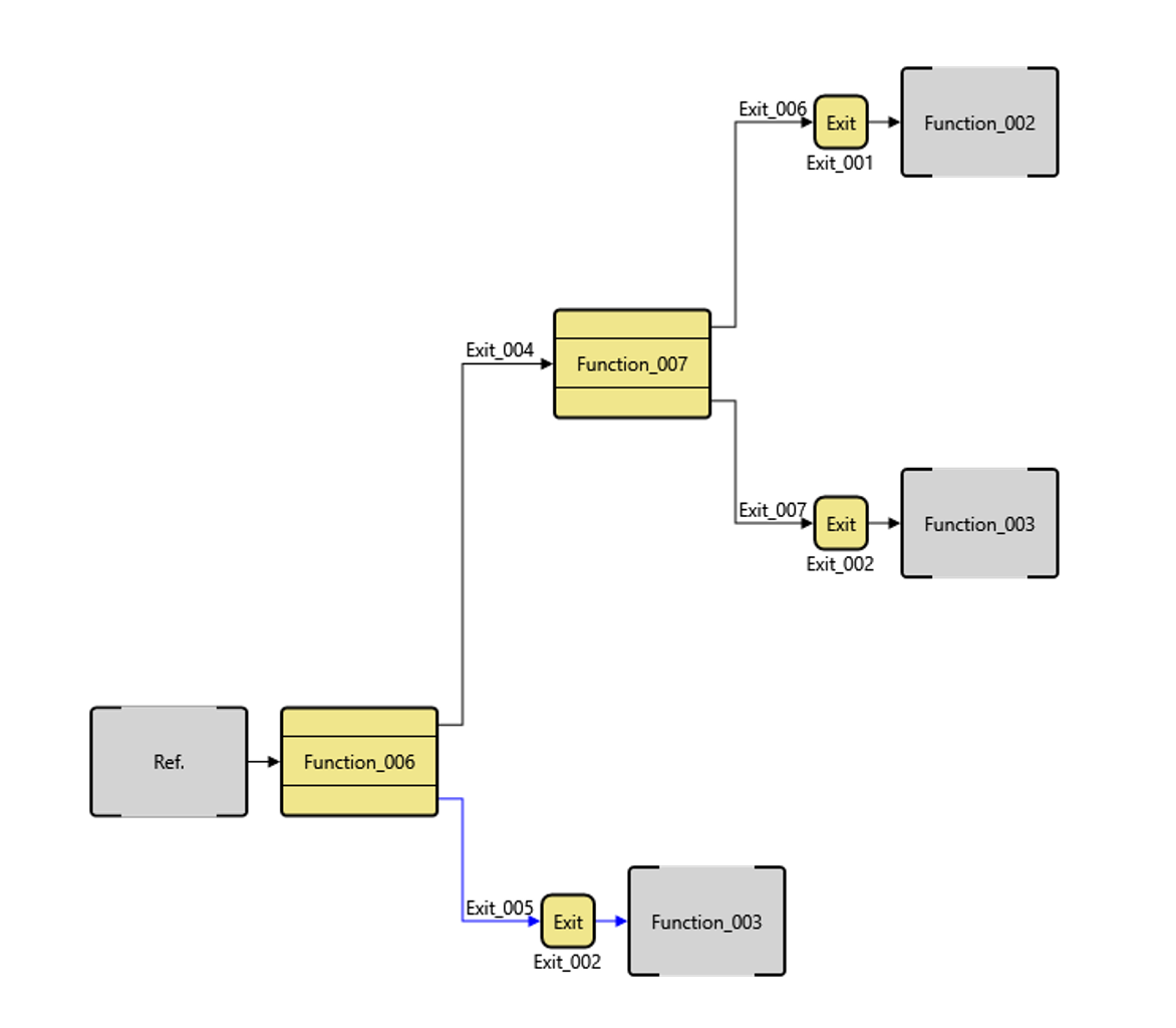
As you can see from the diagrams, in order for the path that will execute Function_002 at the higher level to be selected , Function_006 will have to select Exit_004 (remember, exit’s represent some decision being made and should be named to make that decision result clear), then Function_007 would have to choose Exit_006, otherwise Exit_007 would be chosen and then Exit_002 would be chosen at the higher level and Function_003 would be executed at the higher level. Now let’s look at that graphically:
Which will result in the execution of Function_002 at the higher level:
The graphical representation is much easier to grasp. I think you can start to see the value of being able to decompose a function that’s deciding something into lower levels that synchronize with the higher levels. Try this out for yourself in the simulator. The best way to learn is by doing.
My goal with this article was to demystify the use of Exits for GENESYS and CORE users. I hope that this little tutorial has helped that cause a little bit. Exits are really not hard to use, can add so much to your model, and yet are the most under-utilized constructs by those new to modeling. Capturing the decisions your system is making is a critical aspect of good systems engineering. Capturing decisions can lead to deriving a better set of requirements as you decompose your systems behavior. Each of those criteria that result in the decisions should be captured in functional requirements. The behaviors associated with resultant decisions should be captured as requirements as well. Laying out the Exit behavior in your models will greatly enhance your understanding of the system. Go forth, make Exits, and model your systems’ decisions!


Hi Andy,
Fantastic post. I had asked about using exit conditions vs. select constructs a few weeks ago in the “See It” presentation. You cleared up the differences then, but this post helped add a lot more information and rationale.
It seems like with both exit conditions and select constructs, only one path can be taken. How do we show that multiple paths may be taken? For example – given five different paths, we can take one, we can take five, or we can take any number of paths between. How would you show it with both select constructs (probabilistic) and exit conditions (logical)?
Thanks!
Great question! The short answer is you can’t! 🙂 The 2nd part of this post goes into that very topic, and provides a thorough answer. Fair warning, I make analogies to programming concepts…
https://systems-wise.com/exits-the-sequel-now-with-loops/