

Chapter 4 of the INCOSE Systems Engineering Handbook (4th ed.) provides a thorough discussion of “Technical Processes for the System Lifecycle.” The first two technical processes are (i) business or mission analysis and (ii) stakeholder needs and requirement definition. Each of these processes leverages engagement of system designers with business and/or stakeholder groups to ensure the design team has a firm understanding of stakeholder needs for system design.
The American Society for Quality (ASQ) recommends using affinity diagrams to organize ideas into their natural relationships whenever you are confronted with the following conditions:
- many facts or ideas appear to be in chaos
- an issue seems too large and complex to grasp
- group consensus is necessary
These conditions sound an awful lot like the conditions we commonly encounter when starting a system design project – seemingly random requirements and desires, an overwhelming number of requirements, and conflicting needs from different stakeholders. So the natural questions are: “How can I use affinity diagrams as a system engineer?” and “How can I capture this in my design model?”
The method or process for creating affinity diagrams is commonly known as the K-J Method, named after its inventor Kawakita Jiro. The basic process for developing the affinity diagram is to leverage a focus group of experts (i.e. stakeholders) to record ideas on cards or sticky notes, then to organize the ideas in some set of related ways, and finally to reach group consensus of the categorization.
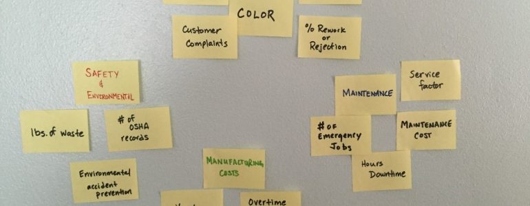
Leveraging the example from the ASQ webpage on affinity diagrams, let’s suppose, for example, that we gathered a focus group of stakeholders to determine the key requirements for a new system design. This group identified a set of requirements which they placed on sticky notes (a common substitute for index cards) and placed them on the conference room wall as shown in the following picture:
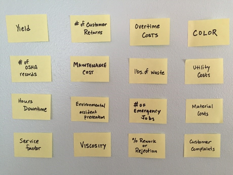
Figure 1. Stakeholder Needs
Our challenge is to capture this information in our MBSE model so that we can provide full traceability of our system design back to these original stakeholder inputs. The first step would be to capture each of these entities in the Requirement class (preferably with an agreed upon description clearly stating the need consistent with best practices per INCOSE’s Guide for Writing Requirements.) In the image from GENESYS (shown below), I created a package entity named “Stakeholder Focus Group Needs” and, using the package diagram, I got the following visualization:
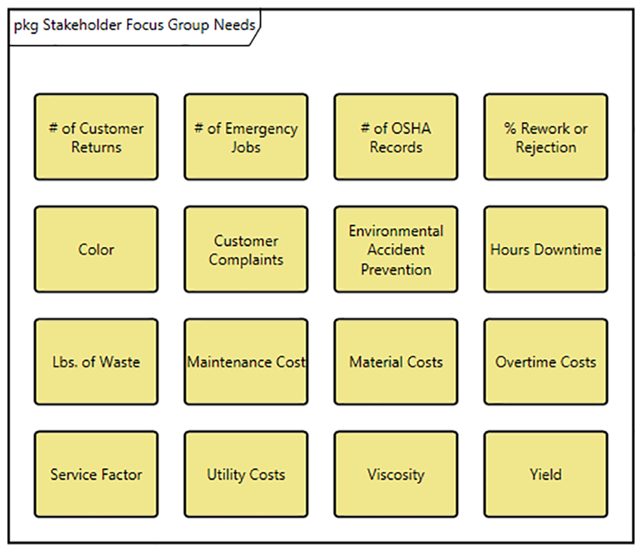
Figure 2. Stakeholder Focus Group Needs
This diagram looks remarkably similar to the picture taken from the conference room wall. The order of the entities is different, but at this point, the “needs” are not grouped.
When the stakeholder group gathers at the next session, the goal is to group the entities into subsets of related needs. The group goes to work accomplishing this task and changes the conference room board as captured in the following picture.
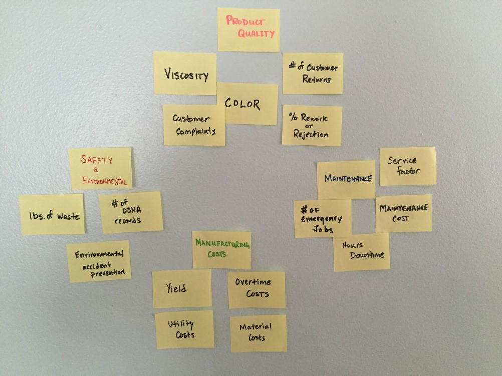
Figure 3. Grouped Stakeholder Needs
To capture the groupings of the stakeholder needs, I create a set of entities in the Category class and relate each of the needs captured in the Requirement class earlier. Each unique categorization (Product Quality, Maintenance, Manufacturing Cost, and Safety and Environmental) is captured as a separate category in the model.
Next, I created a custom hierarchy named “Affinity Diagram” using the relations “includes” and “categorizes” to draw a diagram of each grouping. An example from the Maintenance category follows.
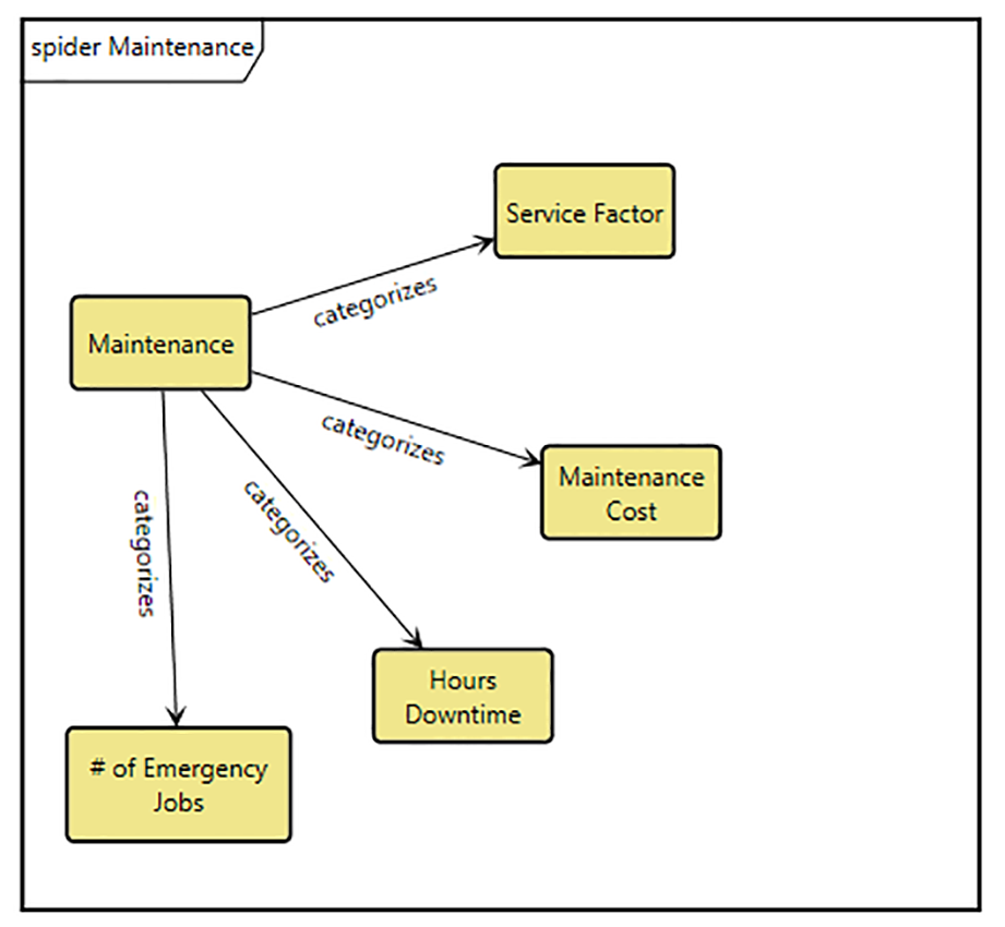
Figure 4. Maintenance Needs
We can show all of the customer needs on one diagram by creating an overall category named “Stakeholder Performance Measures” and have this category include each of the categories previously identified. Then, using the custom hierarchy already developed, we can use a spider diagram to generate the following visualization.
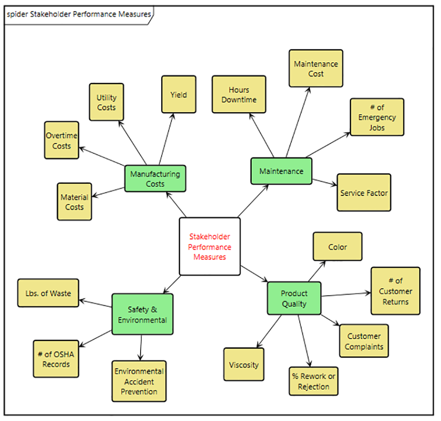
Figure 5. Affinity Map for Stakeholder Requirements
Finally, to provide traceability of the stakeholder requirements from the model back to the original source, we can create a Document entity, “Stakeholder Performance Measure Development” to document the initial contributions of the stakeholder group.
As stakeholder communities grow or requirement sets become more complex, applying the affinity diagramming process becomes a very useful method for structuring the initial stakeholder inputs and for documenting stakeholder needs in a structured manner that increases full-team comprehension. These simple steps provide a powerful method for capturing the artifacts from the requirement discovery using affinity diagramming. By applying the concepts developed here, a user can organize and capture the result of any process used by your team during the engineering of your system.


