

NOTE: In part 2 of our application of CSDL blog, we will start where we left off last week. Using the concepts of CSDL applied to a high-level medical device model, we took some originating requirements that we modeled and created and related a significant piece of the physical architecture of the system of interest and roughed out an interface definition quickly. Today we will model more details of the physical interface which will provide us a bridge to defining behavioral architecture by following the logical flow of the CSDL meta-model, then complete the union of the physical and behavioral descriptions traced to the requirements connecting what they system is, what it does, and why it exists.
MORE INTERFACE DETAILS
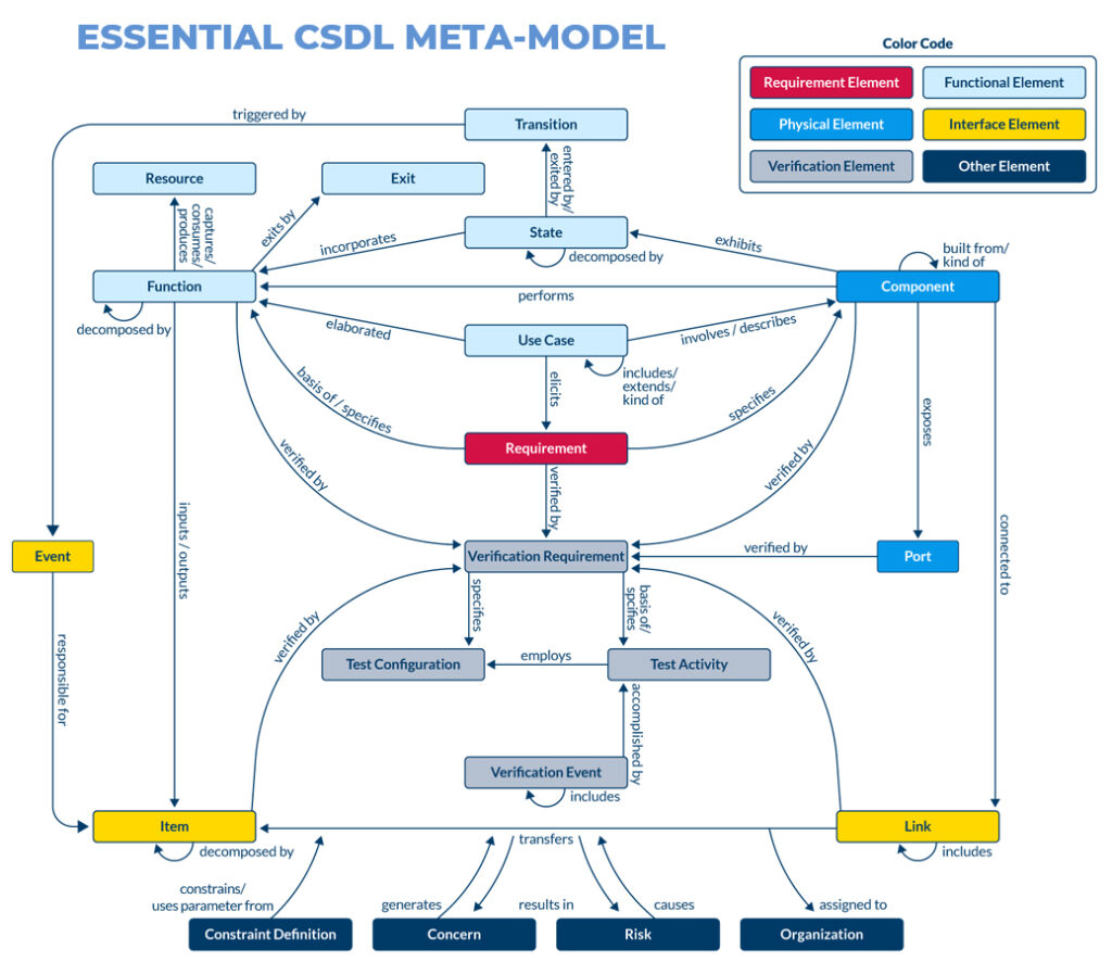
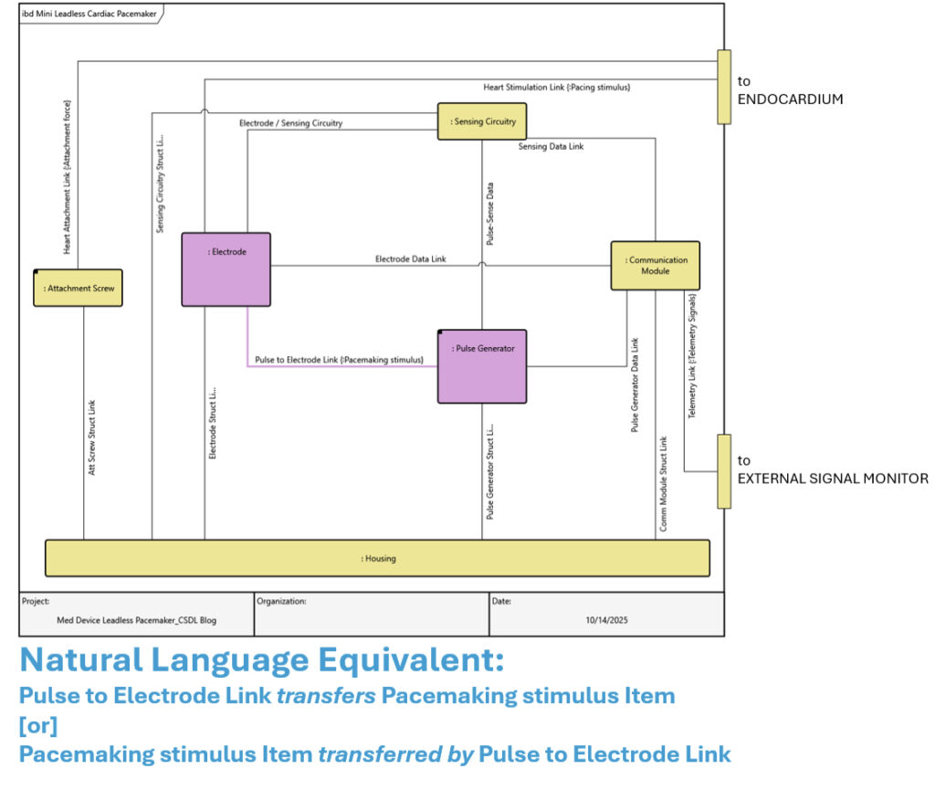
To better specify the interfaces, we could describe the nature of the interfaces in more detail. What electrical signal is exchanged between the Pulse Generator and the Electrode, for instance? The CSDL meta-model indicates that a Link entity representing an interface can be informed with one or more entities of the Item class, and transfers/transferred by relates these two classes. An Item can be anything that crosses a Component boundary, such as data, signals, forces, or even physical objects. In this case, our Item will be an electrical signal called Pacemaking stimulus, which will be transferred by the “Pulse to Electrode Link”. A Flow Internal Block view can help us visualize this:
ITEMS AND FUNCTIONS: PRIMARY PARTS OF BEHAVIOR
In a well-defined system, Items should not just spring from nowhere. Recognizing that Items are essentially inputs and outputs of our system, the process that transforms inputs to outputs within our system are entities of the Function class. The CSDL meta-model indicates that we relate Functions to Items with the input to/outputs relationship.
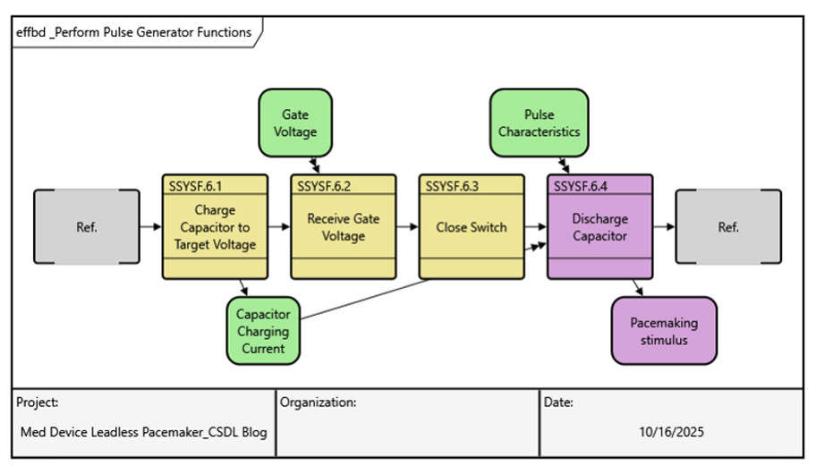
Now we are beginning to describe the behavioral architecture of this pacemaker, “what the system does”. Functions can be ordered hierarchically with the decomposes/decomposed by relationship, but it is much more descriptive to represent the logical flow of Functions throughout the system with a set of structured representations. GENESYS has two views that illustrate this: the Activity Diagram and the Enhanced Functional Flow Block Diagram (EFFBD). Each has its own merits, but generally the EFFBD is best suited for a general audience while still representing function and item flows. Leaving the full explanation of the executable constructs we can use to describe the system behavior for a future blog, at a high level, we can show a simplified EFFBD representing an intended behavior that creates the “Pacemaking stimulus” Item.
ALLOCATING THE FUNCTIONS TO COMPONENTS – CLOSING THE LOOP
Now that we have some definition in pieces of the physical and behavioral architecture of our system, we can close the loop and join them by ensuring functional allocation. It should make sense to us that a particular system behavior (Function) cannot be enacted without a physical entity (Component) to do it, and any Component we define in our system that doesn’t contribute a Function probably should not be in our design model. The CSDL meta-model indicates that we relate Functions to Components with the performs/performed by relationship – this represents functional allocation.
Looking at the same EFFBD, we can allocate those Functions to Components that exist already in our system model. The capacitor charging function can be allocated to the Battery component that already exists, and until we know more, we can allocate the remaining functions to the Pulse Generator.
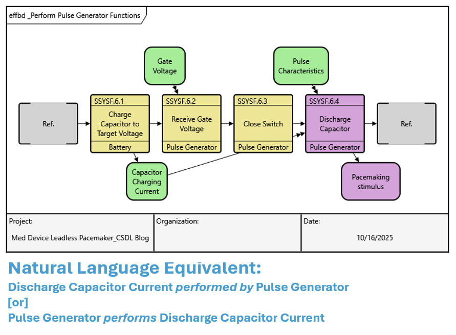
This EFFBD suggests we could add a MOSFET Component to the system model if we feel it’s informative – this is a natural way that models evolve. Adding detail to one piece will uncover more modeling work that can be done. For our purposes, we can pause here and see what we accomplished implementing the entities and relationships inherent in the CSDL:
- Acknowledged a requirement for a self-contained battery and created a Requirement entity in our model
- Created a “Battery” Component entity and related it to the Requirement utilizing the specified by relationship
- Recognized the battery is part of a physical hierarchy, it decomposes a subsystem we represent with a “Pulse Generator” Component entity
- Established the electrical interface between the “Pulse Generator” subsystem and the “Electrode”; both are connected to the same Link entity
- Informed the “Pulse Generator to Electrode Link” with a “Pacemaking stimulus” Item it transfers
- Built out a simple, linear functional flow that outputs the “Pacemaking stimulus” Item
- Closed the loop by allocating the proper functions in that flow to the “Pulse Generator” subsystem (and saw that there might be more modeling work to do!)
CONCLUSION
The CSDL is not just a modeling language we can theoretically use to describe what a system does, what a system is, and why it exists. The natural language ontology serves a practical purpose in developing the how/what/why of a system quickly in the way many engineers think about and communicate system development tasks. The essential meta-model presented here shows that other foundations of Systems Engineering can be joined into our architecture descriptions: Use Cases, Verification/Validation, System States, and Risks/Concerns to name a few. Next time, we’ll delve into how the CSDL schema can be modified and extended to align with how your organization thinks about these SE foundations.


