

We’re told risk is at the interface. But, the term “interface” conflates many ideas, and we often focus on the wrong problem. To correct that, we should consider three perspectives on connectivity: logical connectivity, physical connectivity, and behavioral connectivity.
Allow me to demonstrate with an example of a multi-point message exchange.
Logical Connectivity
As we sit at our workstation writing an email, we are notionally thinking that there is some connection between us and our recipient, as depicted in the figure below. We don’t need to know a lot about networking technology to know that the e-mail will get there. This is the essence of a logical connection.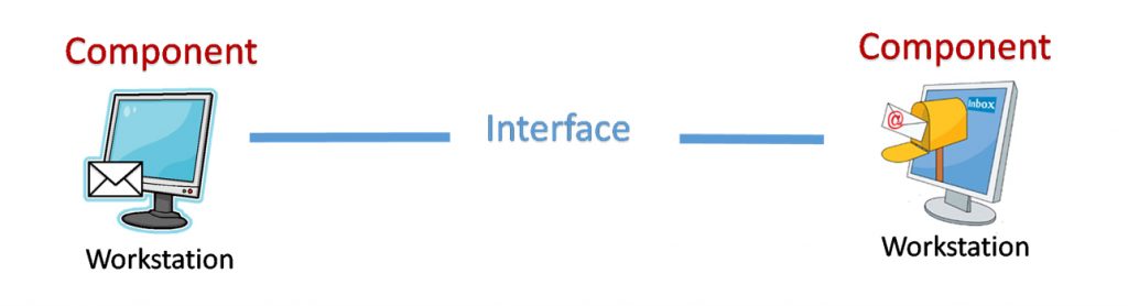
In a multi-point message exchange, we have one message being sent to three consumers. Even though only one message is being sent by the producer, the producer has three logical connections: one logical connection per consumer as shown in the figure below. It may be natural to think of this as a single interface originating from the producer and splitting before connecting to each consumer, tracking the way the message will travel. The point of a logical connection, however, is to merely indicate that the producer has three conversations with three consumers, even if it is the same conversation duplicated three times.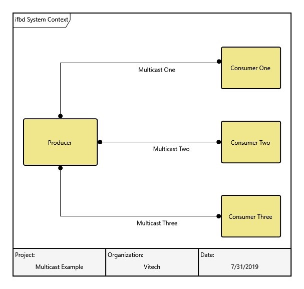
Physical Connectivity
Meanwhile, back at our workstation, we know that our computer is connected to a local network, either hard-wired or via Wi-Fi. And, we know that ultimately there is a telecommunication network that routes our email to our recipient’s local network. This chain is depicted below. These connections, while still abstracted to a certain level, represent physical connectors that help us realize a logical connection. That’s the essence of a physical connection and its association to the logical perspective.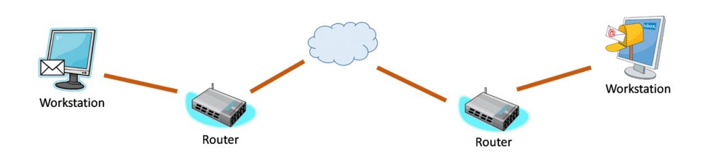
In our multipoint example, the physical connections can be modeled in a way similar to our email example as shown below, with both the local and wide area networks abstracted to a single network entity.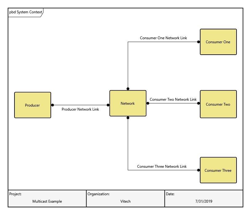
Behavioral Connectivity
The third perspective considers the functionality of the software that sends and receives the message. The multipoint message exchange, depicted in the figure below, shows how a single instance of a “multicast message” is generated and transmitted by producer software to the network, and how software in the network generates a “replicated message” and routes to each of the three consumers. In the behavioral perspective, you can see that the message itself acts as the “connecting” element of the design.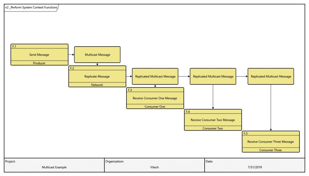
Connecting the Model
Lastly, the three perspective are all related. The logical connection is implemented with one or more physical connections, the physical connections transport our message, and the message is generated and routed by the functionality inherent in the software.
Systems Metamodel
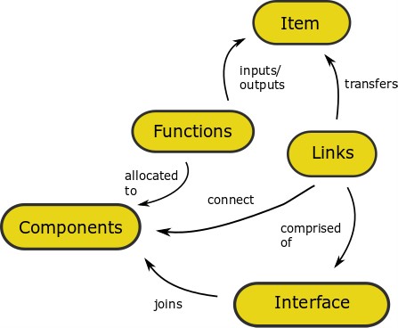
The systems metamodel, as depicted below, supports all three perspectives. In Vitech’s MBSE software GENESYS and CORE, logical connectivity is modeled with the metamodel class “Interface,” physical connectivity is modeled as a “Link,” and behavioral connectivity is modeled as an “Item.” Using the full power of the relationships contained in the systems metamodel, you can be guaranteed that you are considering all three perspectives.
I hope this example helps you the next time you deconstruct your interfaces. Happy modeling!


