

The following is the story of one engineer who charted a clear course through the problems of communicating from her world to another.
Suzanne opened her eyes that morning to a feeling of mixed anticipation and nervousness. The day was here! She looked forward to the challenge but at the same time, the novelty of the situation gave her pause. To this point in her career, she had been involved in “clean sheet” design projects where her team of systems engineers met with stakeholders to elicit requirements for a system solution to a neatly bounded problem. They then took those requirements and used them to design a solution and verify that the resulting system met the originating requirements.
This work was typically done for clients who already knew and understood the process and often had their own systems engineers who worked with her team. The systems produced were constructed of hardware and software, sometimes assembled from off-the-shelf components and sometimes using parts that were custom designed or coded for the particular solution. The team worked closely with the “discipline” engineers to implement the solution. Typically, projects were clean and proceeded more or less as planned. Clients morphed requirements, and constraints appeared in the form of time and budget but, for the most part, there was room to maneuver and accomplish the project purposes.
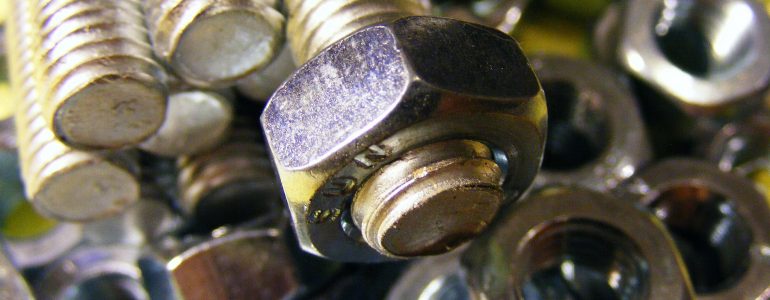
Today, however, was different. Suzanne would be meeting with the owner of an old school manufacturing plant. The business was 75 years old and produced nuts and bolts for commercial applications. Nothing fancy—just straightforward industrial production. There were no complex machines or intricate software—just hot and cold forge lines to turn steel “wire rods” into nuts and bolts. This wasn’t the typical setting for systems engineering work.
The plant owner, Mike, with whom Suzanne would be meeting this morning, was the brother-in-law of her boss. Over the family Thanksgiving table at Mike’s, talk had turned to the nuts and bolts plant. The business was struggling to hold on against foreign competition. Their only hope was to operate as efficiently as possible. Mike could lay off people or attempt to negotiate wages and benefits downward, but before he did that, he wanted to investigate every possible way that he might improve his processes. The demand was there. The only question was who would get the business, and that turned on price which in turn depended on efficiency—being able to maximize what his plant, equipment and workforce could produce.
As Mike talked, it had occurred to Suzanne’s boss that Mike’s factory was a system just as an airplane or a rocket was a system. Mike’s system just had a heavily human infrastructure. His employees made the process go. Any attempt to improve the plant’s efficiency rested on helping the employees improve their own processes. Mike was more than willing to arrange for Suzanne to meet with a succession of plant supervisors and process leads to sketch out a picture of his existing processes.
When Suzanne’s boss had approached her, he and Suzanne had talked about the challenge of improving human processes using the methods and tools of systems engineering as leverage. She had worked out a plan to do just that, and today was the day to move forward. She would lay out the plan to Mike and enlist his support. Then, with his blessing, she would meet with the frontline plant leadership to get a picture of plant operations.
She knew going in that she would face a difficult translation problem. Mike was an expert in the metallurgical processes of hot and cold forging of nuts and bolts, but he would not recognize or resonate with interface diagrams and requirements statements, operational views and parametric diagrams. Neither would his people—the real owners of his processes.
 That’s why Suzanne was armed to the teeth with sticky notes. She knew she would not have clean sheet authority—the luxury of shutting down and starting from scratch. She would have to capture the processes already in place and then improve them from there. That meant she would need to tailor the systems engineering practices to fit this situation and choose her ways of depicting it carefully.
Suzanne pulled up to the plant gate and identified herself to the guard. She had brought along her teammate Alan to help facilitate the conversations, and she handed both of their ID cards to the guard and asked to see Mike. Mike was a step ahead of her. He had notified the guard that she was coming and had an escort waiting. The guard directed her to park and the escort walked Suzanne and Alan to the front office conference room. As they got settled, Mike came in and introduced himself.
They explained to Mike that they planned to get each person they interviewed to talk through his or her process. They would then make a second pass, getting the interviewee to make a sticky note for each step and then put these in process order on the wall. At the same time, Alan would begin to enter the process steps into their GENESYS* systems engineering tool as individual functions in a flow diagram. When they finished, Alan would project the diagram onto the conference room screen, and they would transition their discussion to the diagram and away from the sticky notes.
At this point, they planned to identify the inputs and outputs for each step together with the sources or targets. Some of these would come from another process lead’s process steps and could be connected when those processes were captured in the growing model. Mike liked the idea of beginning with the sticky notes. He saw them as a nonthreatening way to engage the process owners.
They started with Sam McGee. Sam led the prep group that took raw, rolled wire rods from the warehouse and placed them in his furnaces to heat for 30 hours in order to make them malleable for processing. Sam’s crew then dipped the rods in sulfuric acid to remove any rust, and followed that with a water and phosphate bath to prevent further rust. Sam made sticky notes for each step, noting details like furnace temperature and times. In his final step, he delivered the malleable, rust-treated rolls of wire rods to the cold forging group.
That group was represented by Phil Dingus who described a cold forging process where the metal rods became bolts through a series of high pressure manipulations by a series of dies. First, the rolled rods were straightened by a pressure rolling machine and the straight rods were trimmed to lengths slightly longer than the bolts being made. The rods then passed through the rounding dies to make the future bolts perfectly round. The new blanks were then stamped on one end with a set of head-shaping dies to convert the excess length of each piece first into a round head and then into the common hex head.
Phil described how the other end of the blanks were then cut to form a chamfer by the pointer machine and finally how two pressing dies rolled the bolt between them to cut the threads. He made sticky notes for each step and noted the product produced (cut lengths, rounded rods, headed blanks, chamfered blanks and finally threaded bolts) on each corresponding step.
At first, Sam and then Phil wrote, then placed their sticky notes on the wall. Alan then entered these steps into an Enhanced Functional Flow Block Diagram, or EFFBD. Both process leads saw instantly how the flow diagram tracked their sticky notes, even showing the outputs/inputs from step to step. They each identified small corrections to the process, revisions that Alan was able to make and confirm in real-time.
With the addition of the information from Robert Wagner, the hot forge group lead, regarding his hot forging of the nuts to fit the bolts, the EFFBD captured a complete picture of the process from the rolled wire rods to the boxes of nuts and bolts ready to ship. Mike, who spent much of the time observing the exchanges, was impressed at how easily and naturally his process leads had grasped the flow diagrams. The transition from sticky notes to computer diagrams was seamless and took place in real time without interrupting the thought processes.
 Mike was even more impressed that each lead, when he had seen how easily the diagrams could be changed—to add a step for Sam and to reverse the order of two steps for Phil—had begun to make improvement tweaks to their processes despite their investment in long-standing (and relatively unchanged) work patterns. The process leads identified with the process diagrams and seemed to feel an ownership of the changes. This would make the management of the efficiency improvements to a set of time-honored processes all that much easier.
Suzanne explained to Mike that the computer database was absorbing the process information as the diagrams were captured. Control constructs established relationships between the steps and their inputs/outputs. The model would become the basis for the next step—integrating the engineering from the metallurgical, mechanical and electrical engineers who would design the factory line changes and specify the alterations to machines and materials. The engineers would use other, more technical diagrams for their work. Those diagrams could be produced in the same integrated GENESYS model. The model could then become the basis for designing a system that could cut the threads into 400 bolts per minute instead of the 300 that Phil produced currently.
But, that was a step for another day. Today had been a great success. Using the flow diagrams to capture the processes from the process leads’ descriptions had been a great approach. With the sticky notes to start the process, there had been no trouble understanding the diagrams. The diagrams had captured the process information into the database and laid the groundwork for more technical design considerations. Using intuitively understandable views, factory process leads had created the process framework for a sophisticated engineering model.
As she started the car, Suzanne exchanged grins with Alan. The dialogue with the process leads had been a good one. They pulled through the factory gate already thinking of their next steps.
Suzanne and Mike’s satisfaction with the day came from their success in eliciting the processes from the process owners in a way that resonated with the sources without requiring lots of translation or explanation. Sam and Phil and Robert—and Mike for that matter—had all identified quickly with the flow diagrams, recognizing their processes in the depictions. Even though the diagrams were simple enough to be grasped quickly, they were part of a powerful tool that used them to ingest the information about the logical structure of the manufacturing processes and assure that any changes were reflected instantly across all views. In addition, the logical structure that was captured and verified by the process owners was available to use as a basis for expanding the model to include the physical mechanisms by which the process steps were performed. The use of the tool enabled the process owners to be easily integrated as full partners in the design and improvement effort.
*GENESYS is a Vitech software engineering tool.


