


Systems engineers and systems architects have many architectures of which they need to be aware: there’s the architecture of the system-of-interest (or system under design), the architecture of the larger system in which the system-of-interest must operate (the context system), and the architecture of the enabling system (the enterprise or organization). Having a good understanding of each of the external architectures is critical to developing synergistic solutions that operate harmoniously with each other in intended ways.
However, there’s another architecture that systems engineers using MBSE methods must not only acknowledge but also consciously design and implement: the architecture of our system models themselves. This may be a single model, a collection of models, or a set of MBSE models operating within a larger digital engineering environment, depending on the application.
Initial Considerations: Surveying the Landscape
If the team is building a one-off, unique product for a single customer without legacy MBSE models upon which to draw, the systems engineer may be able to jump more quickly into modeling. A single model containing all aspects of requirements, behavior, structure, and verification and validation up to the agreed-upon scope may be the right approach. However, in many other applications, it isn’t that easy. In an increasingly complex world comprised of enterprises with multiple product lines, each going through constant upgrades, and with customers sometimes demanding inclusion of optional features or customizations, the way in which we as systems engineers capture this information in our models can become overwhelmingly complicated and increasingly less manageable if we’re not careful in how we structure our modeling architecture up front. Just like everything else in systems engineering, spending some extra time up front to understand the problem and develop thoughtful responses that meet the defined needs pays off in the long run.
One way to visualize this problem is as a multi-dimensional enterprise context graph, such as the one below.
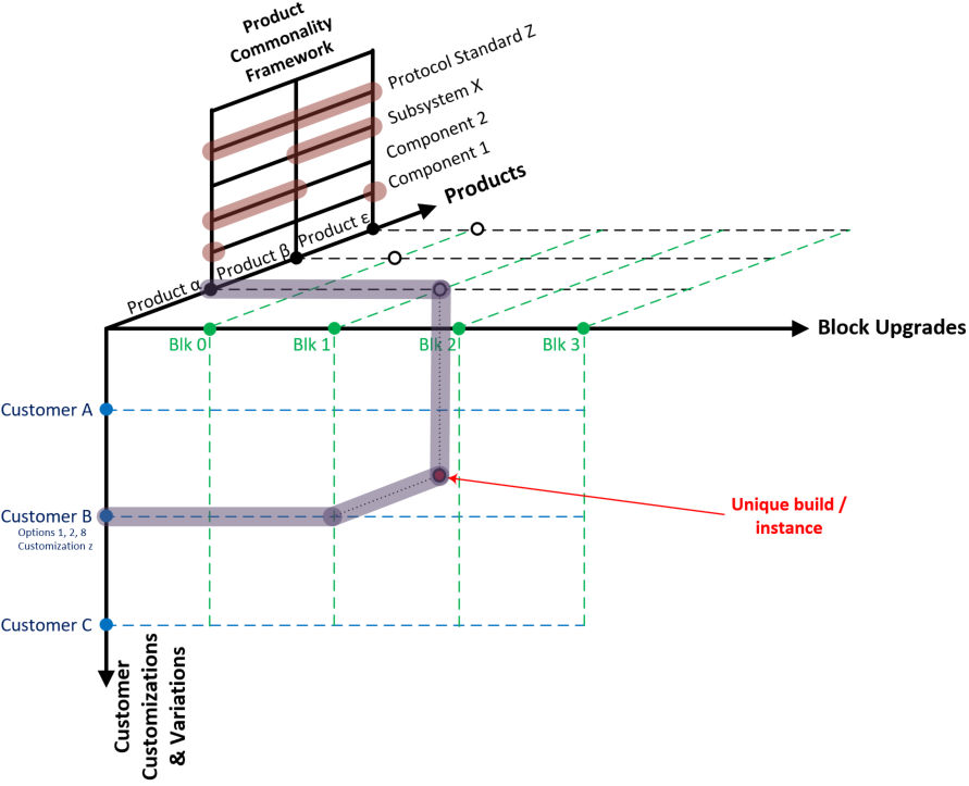
Figure 1: Multi-Dimensional Enterprise Context Graph
In this diagram, we are showing that any unique product build is defined by the selection of a particular product within the product line, the specific block or version of the product selected, and any particular customizations or special feature requests made by the customer that have been approved. The combination of the items that go into the unique build instance results in what actually gets delivered to the customer. Also shown is a relationship framework between the products, displaying how commonality of components, subsystems, standards, or protocols are mandated. The unique set of requirements, behaviors, structure and V&V plans for that unique build are those defined by product and build as the baseline, modified by either additions, modifications, or subtractions specified by the customer.
This diagram just shows one way of visualizing the multidimensional program space that affects model architecting. There are certainly other models and frameworks that are valid. The one above may not apply to every company’s business model. The dimensional elements and terminology should certainly be tailored to your enterprise’s unique needs, but the exercise of documenting what is important and developing an understanding of the dimensional elements and their interrelationships is the key first step to undertake when developing an MBSE model architecture implementation strategy.
Why It Matters
Why should we even care about defining the enterprise problem space this way? Well, systems engineers must understand that there are different objectives for different stakeholders. A customer typically only cares about the end product – they want to know the product, the version, and unique features and customizations that they’re getting. Or if it’s a customer-funded new product development, they may be specifying their needs up front, and a new product may be developed.
Internal stakeholders, such as the C-suite staff, product line engineers, and program managers may be much more concerned about minimizing development costs and reusing existing solutions as much as possible. As systems engineers, we do not want to model the same concept more than once, as it becomes a configuration nightmare and violates one of the fundamental MBSE concepts of “one idea in one place.”
If we look at one viewpoint while ignoring the others, we may develop our models in very different ways, resulting in potentially masking the valid concerns and needs of a stakeholder group, or partitioning our models in a way that isn’t conducive to answering the questions most important to each stakeholder group.
Partitioning Model Content
Once the questions of modeling scope and purpose are answered, the next question that must get addressed is how and where to partition model content to meet the overall objectives.
In GENESYS, we have several tools at our disposal that can help with implementing a modeling architecture framework. Some of these are the ability to generate multiple projects, reuse content from one project in another via cross-project relationships, import content from one project to another, versioning, baselining, and permission controls.
Let’s take the example of an electric car company that has several car models, each of which gets a minor cosmetic upgrade yearly and a major upgrade every five years (including chassis and powertrain), and provides customers a number of optional packages and features. As batteries are a large cost driver, the company wants to use common cells across all models for a given period of time, then inject new cell technology at major upgrade cycles. They also wish to use common CAN bus hardware and protocols for all of their vehicles so that microcontrollers and sensors can communicate in a common way, streamlining the associated software development effort.
In this case, I may choose to create separate projects for components that get used in multiple car models. I might decide to have a series of component or subsystem models for elements that get used in multiple models – for example, there could be a battery module project if that’s the highest-level reusable assembly in the electrical power subsystem. I might also choose to have a CAN bus network pattern project. Each particular implementation of CAN may be unique in terms of microcontrollers and sensors, but I may wish to create a reference CAN implementation pattern project that would show how CAN buses, microcontrollers and sensors are connected at this company. It could also include standardized commands, queries, data formats, etc. Those models might be owned by the designated subsystem system engineer, and write access may be limited to a few members of those design teams.
I could then decide to create a project for each car model. These would then utilize the component projects, such as the battery module project, as needed, via the establishment of cross-project relationships, as shown in the figure below.
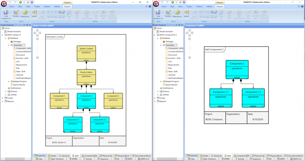
Figure 2: Utilization of Cross-Project Relationships
In this way, the car model systems engineers can use the component projects, but are unable to modify them alone. This maintains configuration control and ensures that designated responsible engineers maintain control of their content.
I could then also import the CAN bus pattern project into my car model project. The CAN bus pattern project would then act as a reference and example for the car model systems engineers when integrating the communication subsystem. The CAN bus pattern project could consist of a package with a generic reference implementation showing how every unique element interfaces and communicates. It might also include customizations to the schema to capture additional attributes for message Items that are important.
Options and customizations could be handled within the car model projects. However, if Shaquille O’Neil decides to order a vehicle and is willing to pay enough for non-standard modifications, that may require a separate project altogether, as his unique accommodation requirements might well invalidate other standard model and version requirements for the vehicle. Developing a distinct project for Shaq’s project could be the best way to handle it, as it’s a unique one-off request and requires a thorough review of all previously baselined requirements and design decisions. Because the company has no plans to develop a standard model variant for 7’ clientele, it may be best to isolate that work in its own project so that it doesn’t create additional model confusion with the standard products.
Versioning and baselining of models can be used to maintain configuration control. Baselines can be used to capture each major block upgrade when complete. Additional permissions can be set to give sub-teams rights to author particular sections of the model while restricting their abilities to modify content elsewhere.
This is just one potential solution. Yours may be very different based on the unique needs of your organization and active projects. However, having a clear approach to generating and maintaining your models is important. Once the approach is developed, it should be documented and clearly articulated to the rest of the team so that they understand the approach and the rationale behind the approach. The approach should be revisited periodically, as the needs and objectives of the enterprise will continue to evolve over time.


