In Part 1 and Part 2 of this series, we covered the first six of our nine laws of effective systems engineering. Law #1 – Begin with the End in Mind; Law #2 – It Doesn’t Help to Solve the Wrong Problem; Law #3 – Insight Is the Goal; Law #4 – The Model Is the Main Thing; Law #5 – To Catch (Design) a System You Have to Think Like One; and Law #6 – It’s All about Relationships. In this concluding post, we will revisit the final three:
Law #7 – Even a Set of Views is not a Model
Law #8 – Choose the Representation that Best Suits the Audience
Law #9 – Systems Come in 3s
Law #7 – Even a Set of Views is not a Model
With the rise of model-based systems engineering, we run the risk of inadvertently substituting a decoy and dangerous approach—diagram-based SE—in place of the powerful models we need. However, much as top, side, and front views in mechanical engineering are simple projections of an underlying model, the myriad of traditional and object representations are limited views of the underlying system model.
These projections are made from a model. Where they are created and maintained separately (as with numerous drawing tools), the model is in the head of the draftsman creating the view. Control over change and consistency emanates from the same source. Where design is collaborative and team-based, there are as many models as there are cranial repositories. Not only does this not promote consistency, it works against it. No matter how many views are produced from these sources, they do not aggregate themselves into a single coherent model.
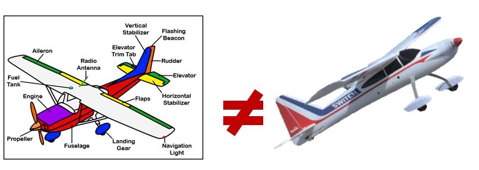
A true model depends upon control constructs and relationships (see Law #6) webbing the system entities together into a model of the system solution. It is the entities, their properties and relationships, and the definition of their interactions that make up the model. Individual views provide valuable analytical insight and aid in communication, but they are defined from a singular viewpoint. Without a coherent model at the foundation, diagrams are simply static representations from a fixed viewpoint. While it is important to be able to see and represent this in order to understand and evaluate the design, the representations are no more the model than a schematic of a model airplane is the model plane itself.

Flat diagrams are not models.
Often times, teams will rely upon an underlying data dictionary to “align” an independent library of pictures and assert that the result is a model. But remember Law #6—it’s all about the relationships. Classically, different representations focus on different perspectives (and different relationships) of the system in question. Data dictionaries may align object names and properties, but the relationships—the critical aspect in question—are left to vary from diagram to diagram. Predictably, the result is an inconsistent, incomplete, and often incoherent picture as the complexity of the system and the desired viewpoints overwhelm our human ability to manually align these disjointed artifacts.
Ultimately, the model is a tool for understanding the problem and reasoning through the solution space. (Law #4) For example, the model provides a reasonable context for trade studies. That means that no collection of views, no matter how robust and fit for their purpose, can become the model itself just as no collection of photographs and assembly directions can become a model airplane.
So how does this happen? A truly robust modeling tool, like Vitech’s GENESYS, is underpinned by a system metamodel which establishes the framework in which the model is captured. Rather than relying on a number of disconnected views, it contains a complete model of the system. Views can then be projected from it and any changes to them are transmitted to the model itself, maintaining real time consistency. The model can be used to simulate the design’s behavior, conduct trade studies and make predictions about the system’s ability to meet the requirements that drove its design. Without the metamodel there can be no model, and without a robust model there can only be at best a partial understanding of the design.
Law #8 – Choose the Representation that Best Suits the Audience
The role of any representation or view is to convey a particular subset of information to the intended audience in order to enhance their understanding of the system solution. Most often, representations are used by the design team to gain perspective and understanding of the model and its interrelationships. By selecting the desired viewpoint and representation, the team can gain insight and understanding of the model suited to their particular purpose.
Representations can also be used by the team to communicate information about the model to others. Communication requires meeting the audience where they are and bringing them to the desired understanding. By considering both the situation of the audience and the team’s need for audience understanding of the model, it is possible to choose the view or views that will achieve this goal.
For example, a group of process owners will usually resonate more with functional flow representations than the UML-based representations that reach the object-oriented programmers involved in the design. Sequence diagrams, where time flows from top to bottom, may confuse an audience accustomed to flows plotting time from left to right. This does not make a particular representation good or bad but rather simply not fit for purpose with a particular group. The goal is to present information in a way that is most likely to reach a specific audience. The first consideration then is what view or views the audience is most likely to understand, given their roles and experience.
The second consideration is what the audience needs or wants to know. By providing information that the audience is looking for, the communication channel is opened. Additional information can flow through that channel and be received along with the information the audience is seeking. It is helpful to meet the audience’s need for information if for no other reason than to remove the obstacle of open question loops that may obstruct the flow of other information. Although the question “What do you want/need for the audience to know?” is the reason for initiating the communication, being aware of and responsive to audience needs is certain to pave the way to accomplishing the presenter’s purpose.
The final consideration is what the design team wants the audience to know. Choosing the representation rests on the combination of the information that is needed and the ability of the particular representation to communicate that information. Too much information—meaning information not germane to the purpose of the representation—can be as bad as too little. It distracts from the purpose and blurs the message. A good representation includes all of the facts needed to get the points across and adds no more to obscure the message.
Law #9 – Systems Come in 3s
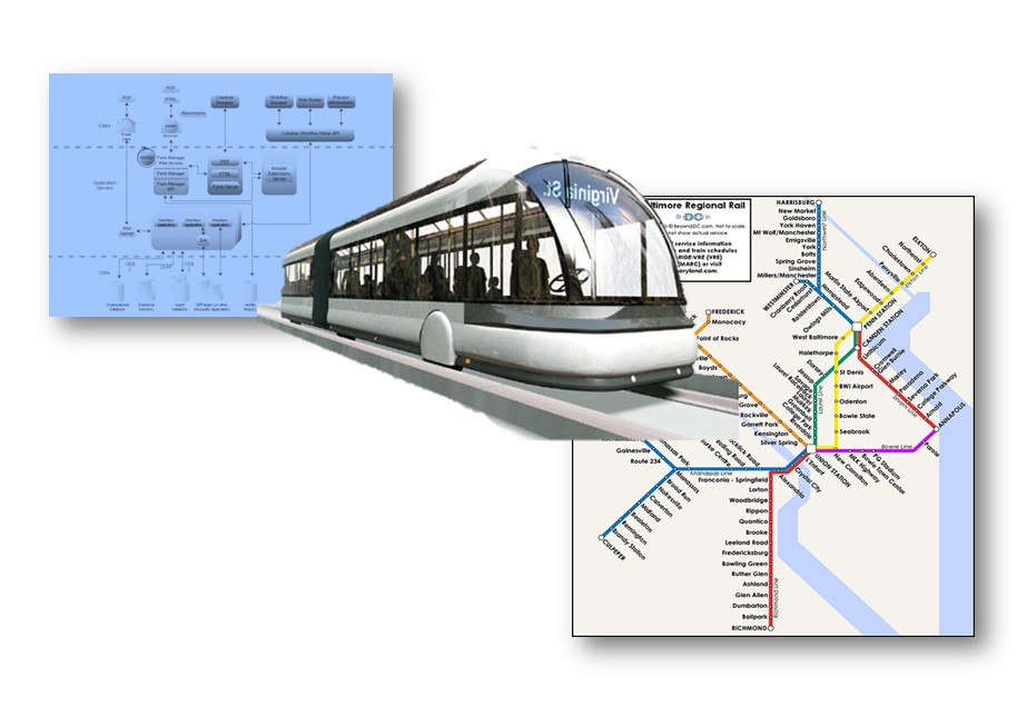
When we talk about systems, it’s all about interactions. Every system design involves three systems: the system being designed, the system it will “live” in, and the system used by the team to design it. Below is the example of designing a subway train. To the right of the train is the subway system in which it will operate, and to the left is the process chart depicting the design process.

Three kinds of systems
Almost all design teams understand that they must focus on the first system, the system of interest. Its design is, after all, the purpose of their efforts. The system under design is the subject of consideration throughout the design process itself.
Many teams, however, fail to adequately consider the second system—the context in which the new system will operate. This failure can lead to unintended consequences and/or inadequacies in the design solution. This system is becoming increasingly important as we design into existing systems and environments. The opportunity to design truly “clean sheet” or “top down” unprecedented systems is becoming increasingly rare. Not many organizations can scrap all the existing technology and processes to accommodate a truly new system. They must retain systems and technology already in place and use the new designs in conjunction with their existing environment. Ignoring this second system represented by the operating environment is a recipe for design failure and implementation problems.
Likewise, most teams do not intentionally factor in the third system—the system they use to design the solution that is the subject of their project—in their design effort. This system typically grows ad hoc from their experience and can be disjointed and uncoordinated. Often the design team mistakenly blends the solution being designed and the design process. That can result in a disintegrated design that impairs real systems thinking (see Law #3). The systems become confused and get lost in the engineering process. Without the rigor and discipline of a well-thought-out system design process, the subject system is placed at risk. The conscientious design team must be intentional about the disciplinary structure they bring to their own processes. This is the system that provides the rigor and process that will guide their design efforts. A failure to be disciplined and intentional here can hurt the design process throughout.
Note: There are other models of this three-system environment. James Martin, in an excellent and detailed treatment of this subject, describes seven systems in this space. Whether one chooses to think of seven systems or three, the critical concept remains—there must be an intentional and rigorous treatment of these aspects of developing the system solution.
In our age of concurrent and connected engineering, it is particularly important that we recognize and deal with all three systems. We must be coherent in the way we provide for all of the engineering, scientific and management disciplines to make their contributions to the design. That can only happen when we provide a design space and tools capable of handling all three systems with balance and intentionality.


