

By Ron Kratzke, Principal Systems Engineer
In a previous post entitled “Variant Management in an MBSE Environment,” I covered the techniques used in CORE and GENESYS to capture variants in the physical architecture.
In this post, I will cover techniques to capture variants of the behavior architecture and development of testing architectures.
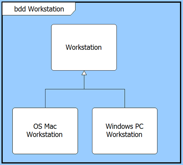
Continuing the example from the previous post, we had two workstation variants, the OS Mac workstation and Windows PC workstation.
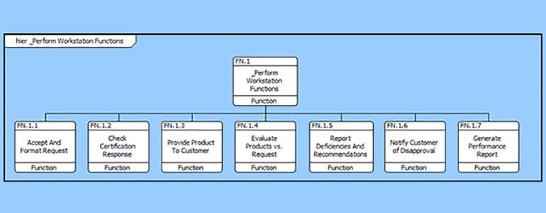
Let’s assume that the “nominal” workstation had the following behavior:
In the OS Mac workstation variant, we desire two additional functions. Let’s call these additional functions Mac OS Add Function 1 and Mac OS Add Function 2.
We want to create the OS Mac workstation behavior to complete all of the functionality of the “nominal” workstation with the included functionality provided by the Mac OS Add Functions 1 and 2.
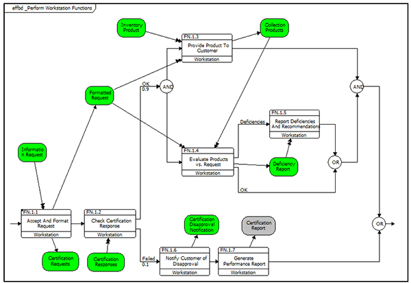
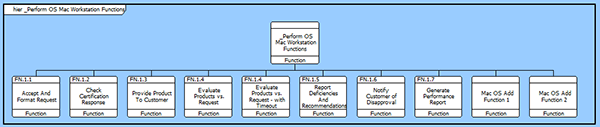
The “nominal” workstation root function (_Perform Workstation Function) is decomposed by all of the functions shown on the EFFBD diagram.
The first step in creating the behavior for the OS Mac workstation is to have the integrated root level function be decomposed by the same functions as the “nominal” workstation. Take _Perform OS Mac Workstation Functions and create the decomposed by relation; then add the two additional Mac OS Add Functions 1 and 2 to this decomposition.
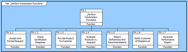
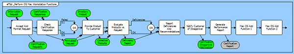
When the decomposition is made, the EFFBD of _Perform OS Mac Workstation Functions does not have the correct arrangement of constructs.
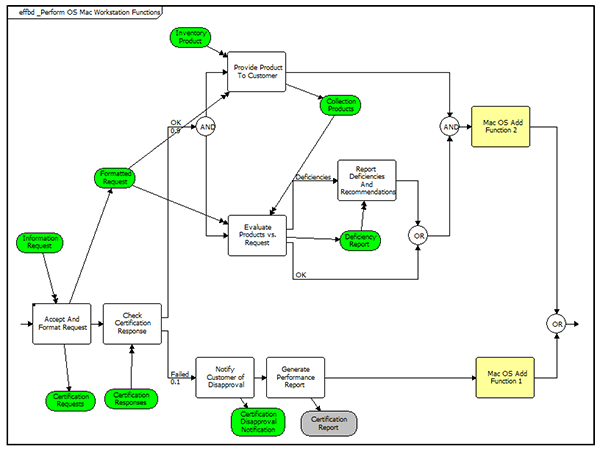
Re-construct the behavior diagram to be similar to the “nominal” workstation behavior with the additional Mac OS workstation Functions 1 and 2 added to the diagram as shown below.
This process can be repeated for the Windows PC workstation. Once both the workstations’ behavior architectures have been developed, the design team can compare and contrast both the physical and behavior architecture.
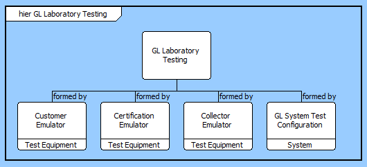
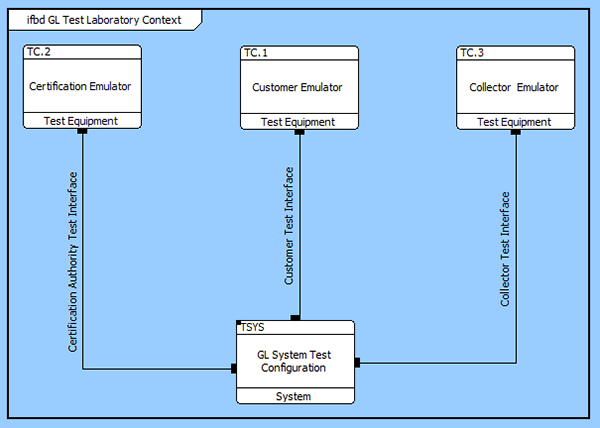
Finally, testing system configuration in a laboratory setting, for example, is common to every system design effort. The Verification Facility provides for identification of the testing configurations using the TestConfiguration class. A VerificationEvent “employs” a TestConfiguration and the TestConfiguration is “formed by” a selection of Components. The Components in the TestConfiguration are a “kind of” Component used in the (more abstract) system design.
The traceability for GL Laboratory Testing is shown by using a custom hierarchy diagram using the “formed by” relation:
Examining the configuration of the Test Laboratory environment from the Component class provides for a detailed examination and configuration of the testing environment. We can develop the Laboratory Context diagram by “building” the Test Laboratory from the Test Equipment forming the test configuration. The Test Laboratory configuration and the interfaces needed to conduct system level testing can then be developed and diagrammed using the Interface Block Definition diagram as follows.
The external component test equipment functionality can be developed using the techniques discussed earlier in this article to document the detailed design of the laboratory test environment. It also follows, then, that the design of the physical test links needed to support system testing can be developed using the workflow and methodology used for more general system design.


