

The exchange of data between model-based systems engineering tools has been an issue for many years within the systems engineering community. Industry, the International Council on Systems Engineering (INCOSE), and Object Management Group (OMG) have all recognized this fact and have attempted to solve the exchange issue in many ways. Still, despite attempts to achieve compatibility (e.g., by using .XML formats when exchanging files), MBSE tools with differing underlying database structures have not been able to attain seamless data exchange. Even worse, many MBSE tools store information graphically and/or do not organize information in a relational database, making the exchange of information nearly impossible.
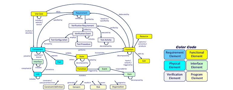
The missing link in the exchange of MBSE information is a system metamodel that sufficiently describes the systems we are modeling and the ancillary information that we want to record during our system development journey.
Until the systems engineering community converges on a system metamodel, exchanging data between tools will be largely manual. While the idea may seem arduous, the MBSE software GENESYS makes this very easy; I’ve input MBSE data from other tools into GENESYS in less than an hour’s time. The following paragraphs outline a process for taking output from a generic MBSE tool and importing it into GENESYS.
The Vitech system metamodel is instantiated in the GENESYS database in the “schema.” Each GENESYS model is built on a schema which organizes the model information in the repository. GENESYS will accept data in comma delimited, .csv format. Most MBSE tools allow this export option. The key to a successful import is to match the data from the other tools to the appropriate GENESYS schema class.
Step 1. Identify and map class elements to the GENESYS schema
As an example of ingesting data into GENESYS, consider the following DODAF/UPDM (or other architecture framework) model of a CubeSat. Let’s first examine output from a sample Systems View Flow Matrix, SV-6, found in Figure 1.
| Number | Resource Interaction Item | Sending System Resource | Producing Function | Receiving System Resource | Consuming Function |
| R.201 | Launch Services Commands | Launch Services | Launch Satellite | Launch Vehicle | Transport Satellite to Orbit |
| R.202 | Ground systems Communications | Ground System | Command & Control CubeSat | Launch Services | Launch Satellite |
| R.203 | Launch Services Communications | Launch Services | Launch Satellite | Ground system | Command & Control CubeSat |
| R.204 | CubeSat Commands | Ground System | Command & Control CubeSat | CubeSat Mission | Collect Science Data |
| R.205 | CubeSat Telemetry | CubeSat Mission | Collect Science Data | Ground System | Command & Control CubeSat |
| R.206 | Mission Data | Ground System | Command & Control CubeSat | Mission Data Stakeholders | Process Science Data |
Figure 1. SV-6 (a)
There are a number of model elements, attributes and implied relationships reported in an SV-6. When reviewing an architecture matrix, or any .csv output, we are first looking for items that align with the GENESYS schema. The first column represents the number attribute of the Resource Interaction Item listed in column two. A Resource Interaction Item represents information that is exchanged between two entities in the CubeSat system. The Resource Interaction Item is best represented by the GENESYS class Item. The two entities exchanging information are listed in columns 3 and 5, and best represented in GENESYS as Components, while their corresponding functions are listed in columns 4 and 6, and represented as Functions.
Figure 2 shows additional SV-6 information. Column 1 lists Physical Resource Flows, defined as a physical interface between two system elements. The Physical Resource Flow best matches the GENESYS class Link. Columns 2 and 3 list the Sending System and Receiving System Resources which represent the source and target system elements connected by the Physical Resource Flows. These are best modeled using the GENESYS class Component.
| Physical Resource Flow | Sending System Resource | Receiving System Resource |
| Launch Services / Launch Vehicle | Launch Services | Launch Vehicle |
| CubeSat Mission / Launch Services | CubeSat Mission | Launch Services |
| CubeSat Mission / Mission Data Stakeholders | CubeSat Mission | Mission Data Stakeholders |
Figure 2. SV-6 (b)
Figure 3 summarizes the classes identified from the source SV-6 information.
| Architecture Element | Associated Systems Metamodel Class |
| Resource Interaction Item | Item |
| Sending System Resource | Component |
| Producing Function | Function |
| Receiving System Resource | Component |
| Consuming Function | Function |
| Physical Resource Flow | Link |
Figure 3. Identifying System Metamodel classes
Step 2. Identify and map relationships to the GENESYS schema
Next, it is important to identify the relationships among the class elements based on the source data. Looking at Figure 1, we first notice that the Resource Interaction Items are being produced by the Producing Function and received by the Consuming Function. According to the GENESYS schema, we can relate the Resource Interaction Item (modeled as a GENESYS Item) as being output from the Producing Function (modeled as a GENESYS Function), and input to the Consuming Function (also modeled as a GENESYS Function). Note that the GENESYS relationships input to and output from denote the roles of the Producing Function and the Consuming Function, so it is possible to model both as Functions generically and still retain their role in the exchange of information.
We learn from the SV-6 data in Figure 1 that the Sending System Resource is associated with the Producing Function, and similarly, that the Receiving System Resource is associated with the Consuming Function. Following the GENESYS schema, we can relate the Sending System Resource (modeled as a GENESYS Component) to the Producing Function (a GENESYS Function) as performing that Function and the Receiving System Resource (modeled as a GENESYS Component) to the Consuming Function as performing that Function.
We learn from the SV-6 data in Figure 2 about the connectivity of the Physical Resource Flow in column 1. In this respect, we can use the GENESYS schema to model both the Sending System Resource and the Receiving System Resource (modeled as GENESYS Components) as being connected to the Physical Resource Flow (modeled as a GENESYS Link). Figure 4 summarizes the mapping of architecture elements to a systems metamodel class and relationship that can be identified from the SV-6 data.
| Architecture Element | Associated Systems Metamodel Class | Associated Systems Metamodel Relationship | Target Class | Architecture Element |
| Resource Interaction Item | Item | output from | Function | Producing Function |
| Resource Interaction Item | Item | input to | Function | Consuming Function |
| Sending System Resource | Component | performs | Function | Producing Function |
| Receiving System Resource | Component | performs | Function | Consuming Function |
| Sending System Resource | Component | connected to | Link | Physical Resource Flow |
| Receiving System Resource | Component | connected to | Link | Physical Resource Flow |
Figure 4. Identifying System metamodel relationships
Step 3. Import source data into a GENESYS model
To ease input of architecture data into GENESYS, first create a new Excel spreadsheet in .csv format with the columns as indicated in Figure 1, above.
Next, prepare a GENESYS Excel Connector table definition to create the mapping for input into GENESYS. An example table definition is shown in Figure 5 below. The table definition is designed to key off the Item element (the Resource Interaction Item) of the SV-6. The first row of the table definition instructs the Excel Connector to ingest the first column as the number attribute of the Item, while the second row of the table definition will ingest the name of the Item. GENESYS will import the Resource Interaction Item as the GENESYS schema class Item as indicated by the checked box in the upper right-hand panel.
The third row of the table definition will import the Sending System Resource as an allocated to relationship target of the Producing Function which is imported in the fourth row of the table definition with the output from relationship. The fifth row will import the Receiving System Resource as an allocated to relationship of the Consuming Function which is imported in the sixth row of the table definition with the input to relationship. Note that the allocated to relationship between a Function and a Component is the reverse of the performs relationship between a Component and a Function.
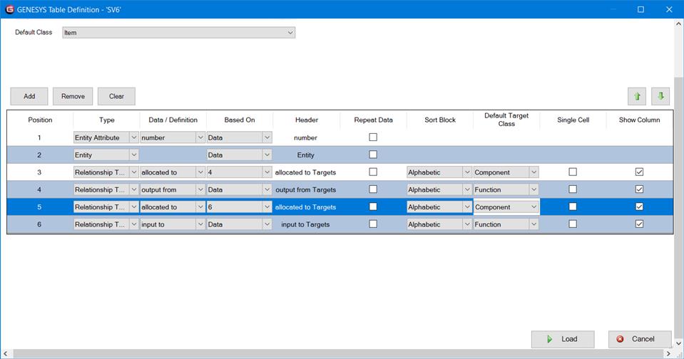
Figure 5. Table Definition
Results of the ingestion as configured in the table definition are shown in Figure 6. Note that the Item, Launch Services Commands is ingested and the input to and output from relationships defined. (Compare with source data in Figure 1.)
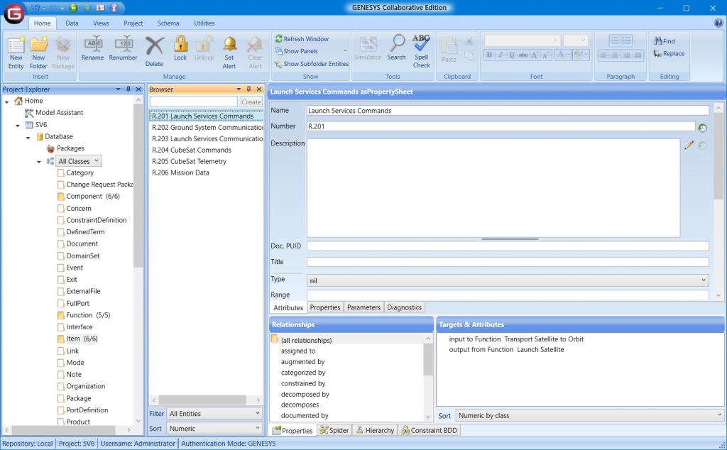
Figure 6. Results of Table Definition Ingestion of Items
We next need to ingest the information found in Table 2. Consider the following table definition shown in Figure 7. The first row of the table definition will import the Physical Resource Flow as an element of the GENESYS schema class Link. Then the second and third rows of the table definition will create a connects to relationship between the Link and to the Sending and Receiving System Resources which were previously ingested as Components.
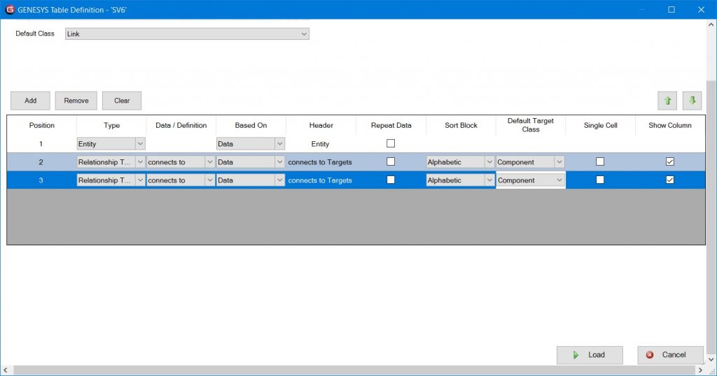
Figure 7. Table Definition relating Links and Components
Results of the ingestion as configured in the table definition are shown in Figure 8. Note that the Link, CubeSat Mission / Mission Data Stakeholders is ingested and the connects to relationships defined. (Compare with source data in Figure 2.)
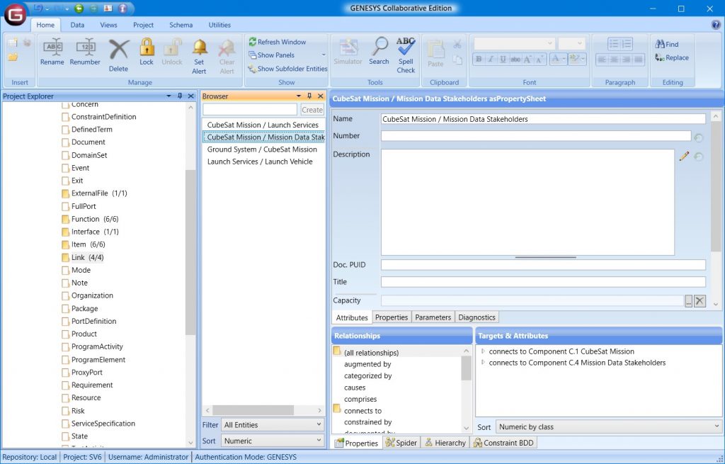
Figure 8. Results of table definition ingest of Links and Components
Other data attributes and relationships contained in the SV-6 data can be imported in a similar way with other table definitions.
Step 4. Add graphically displayed information to the GENESYS model
The biggest hurdle to MBSE tool interoperability is the way many MBSE tools choose to record architectural details. In many cases, information is expressed on diagrams and stored in graphical formats and is not recorded as elements of a database. Nor can it be exported via .csv or some other mechanism.
In our example, the SV-6 is valuable in understanding the architecture of the system, but does not inform us as to the hierarchical relationships among the Components). This is also true for Functions and even Items. Much of this information is embedded in diagrammatic graphics expressed on the SV-2 (for the physical hierarchy) and the SV-4 (for the functional hierarchy). Sample SV-2 diagrams are shown in Figures 9 and 10.
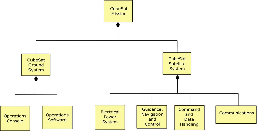
Figure 9. SV-2 for CubeSat Mission
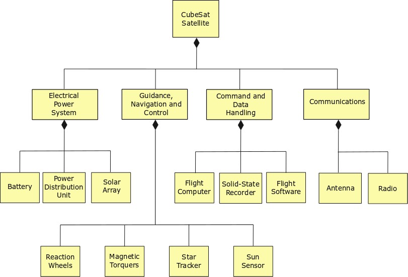
Figure 10. SV-2 for CubeSat Satellite
Information can be gleaned from these SV-2 viewpoints, expressed using BDD diagrams. We note that the Component “CubeSat Mission” has two children: the “CubeSat Ground System” and “CubeSat Satellite System,” expressed with a SysML composition relationship. In GENESYS, rather than rely on graphics to define this relationship, we use the built from relationship to expressly define this relationship using the GENESYS schema.
To ingest this information, we would create a .csv file as shown in Figure 11 and import with a new table definition as shown in Figure 12. Figure 13 depicts the results as ingested into GENESYS. Note that GENESYS can automatically render the BDD based on the data ingested from Figure 11. With a bit more configuration, GENESYS can also render the diagram in Figure 14, showing the behavioral model of this sample system.
| Parent Component | Child Component |
| CubeSat Mission | CubeSat Ground System |
| CubeSat Mission | CubeSat Satellite System |
| CubeSat Ground System | Operations Console |
| CubeSat Ground System | Operations Software |
| CubeSat Satellite System | Electrical Power System |
| CubeSat Satellite System | Guidance, Navigation, and Control |
| CubeSat Satellite System | Command and Data Handling |
| CubeSat Satellite System | Communications |
| Electrical Power System | Battery |
| Electrical Power System | Power Distribution Unit |
| Electrical Power System | Solar Array |
Figure 11. Importing Component Hierarchy Data
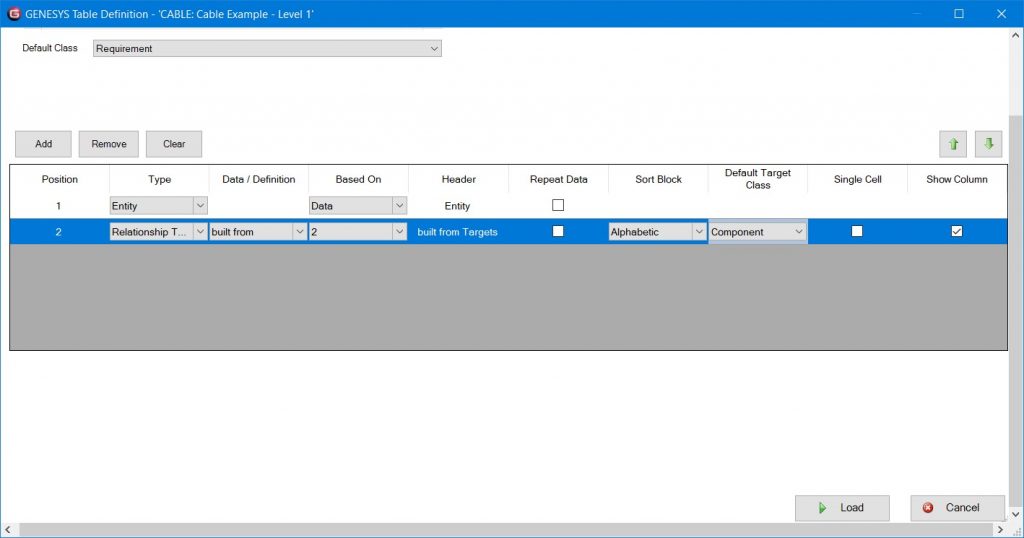
Figure 12. Importing Hierarchical Component Data
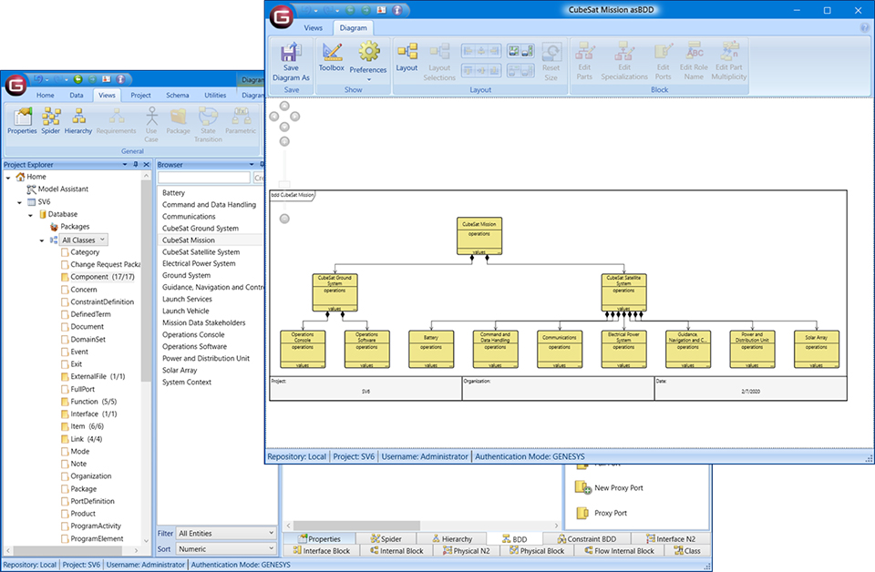
Figure 13. Import of hierarchical design information
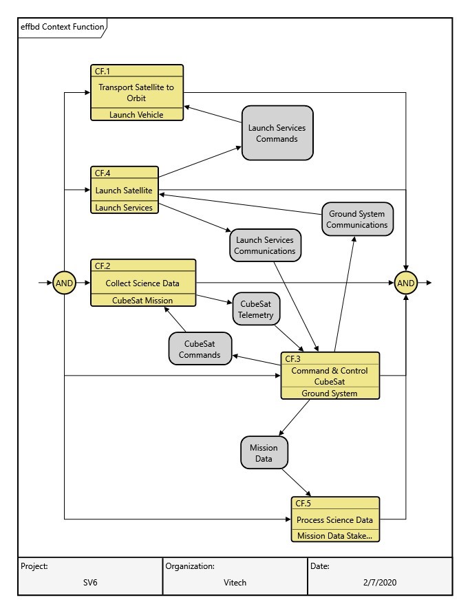
Figure 14. Behavioral model implied with source data
Step 5. Fix inconsistencies in source data
Unfortunately, or fortunately, importing model data from other MBSE tools will usually reveal incomplete models and inconsistencies. Step 5 is conducted in parallel with the previous steps as discrepancies arise. Source data can hide inconsistencies and gaps caused by poor or incomplete modeling efforts. Inconsistencies can also arise between diagrams that attempt to show similar information, but are not caught by the MBSE tool.
In the case of our present example, I effectively created a new Component class element called “System Context” and added built from relationships to the Launch Vehicle, Launch Services, CubeSat Mission and Mission Data Stakeholders Component elements previously ingested into GENESYS. GENESYS then automatically renders the physical block diagram shown in Figure 15. Likewise, creating a new Functional class element called “Context Functions” and adding decomposed by relationships to the appropriate functional elements yields the behavioral model depicted in Figure 16.
Step 5 can extend the time it takes to ingest model data from other MBSE tools, but results in a more robust and complete description of the system.
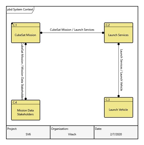
Figure 15. Behavioral model implied with source data

Figure 16. Physical Block Diagram of the System Context
Summary
The Vitech system metamodel is the basis for the schema used in each GENESYS schema. Transfer of information between toolsets will always be difficult and cumbersome until the systems engineering community converges on a standard metamodel that describes the systems engineering aspects of the system we desire to engineer.
The GENESYS Excel Connector is an excellent way to ingest data from other MBSE tools. GENESYS itself also makes it easy to update and adjust diagrams. You can rest assured that the GENESYS schema will keep you straight and you’ll come away with better models of your system.


