


The class diagram displays the static structure and composition of a system. In GENESYS the class diagram allows us to show the Component entities (blocks) that describe a system and display their attributes and operations as well as key relationships among the entities.
The class diagram has its roots in the object-oriented design community. In Object-Oriented Analysis and Design, Booch describes the class diagram as being used “to show the existence of classes and relationships in the logical view of a system.” In Real Time UML, Douglass states that “class diagrams are the single most important diagrams in object-oriented analysis and design. Class diagrams are the primary road map of the system and its object-oriented decomposition.” In UML for Systems Engineering, Holt says that “The class diagram is, arguably, the most widely used diagram in UML.” Though not part of SysML, the class diagram has relevance and value in system design.
In GENESYS, typically the component entity is used to create the abstract representation of a system’s physical architecture which can include both hardware and software artifacts. The hierarchy diagram and the block definition diagram (BDD) are used to present views showing the aggregation and composition of the system. The class diagram is able to present a view onto this physical architecture showing dependencies, associations and generalizations in addition to the aggregation and composition for the system.
The various types of relationships that can be displayed on the GENESYS class diagram can be summarized as follows:
- Dependency: A dependency relationship exists between two entities if changes to the definition of one entity may cause changes to the other. It shows that one entity requires, needs, or depends on the other for specification or implementation.
- Association: An association is an abstract term that can represent any relationship between two entities. An association can be either bidirectional or unidirectional.
- Aggregation: An aggregation shows the formation of a particular entity as a result of one entity being “aggregated” or built as a collection of other entities. For example, a soccer team is an aggregation of players.
- Composition: A composition is similar to aggregation, with the difference being an emphasis on dependence. For example, a house is a composition of rooms. However, if the house ceased to exist, the rooms would no longer exist, as their existence is dependent on the existence of the house.
- Generalization: A generalization is a type of relationship that establishes an entity as a subclass of another entity, the superclass. A generalization implies that the subclass inherits properties and behavior from the superclass. The subclass entity is considered a specialization of the superclass entity. For example, a cat would be a specialization of an animal, where a cat is the subclass inheriting the functionality of the animal class.

A class diagram showing the various relationships that can be represented
Given the class diagram’s roots in object oriented design we can use it to view a GENESYS model representing the architecture of software and software-centric systems in particular. The component entities are used to represent the software classes in the solution. Below is a class diagram for a Button showing its dependency on a Light for backlighting along with all the subclasses that inherit from the Button class. The class diagram also shows the aggregation of the Simple Buttons into the Group Button.
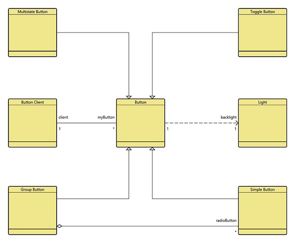
A class diagram for a Button Component
Let us look at how the class diagram compares to the other structure diagrams we have available to us in GENESYS. The structure BDD depicts the component structure from the built from/built in relationships.
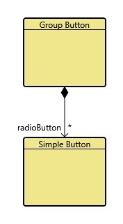
Structure BDD for Group Button
The classification BDD depicts the component structure from the generalization of/kind of relationship.
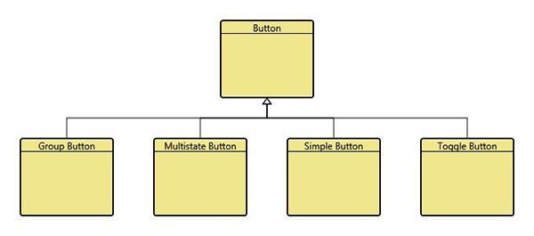
Classification BDD for Button
It’s clear that the structure BDD, classification BDD, and class diagram provide overlapping views of Button, each communicating and highlighting a specific set of relationships and information. The class diagram is a particularly flexible diagram, enabling us to display a number of different relationships and their targets. So given the audience and the complexity you are dealing with, you now have the option of showing more detail with the class diagram, or using the structure or classification BDDs to focus on a particular aspect of the design.


