


In my “other job” as an elected representative for my county, I am often called upon to speak to community organizations and business groups, and to attend diverse events throughout my district and county. Just about any time I am present in a gathering of citizens, the conversation turns to what people do for a living.
Recently at a local cookout/fundraiser, I heard a group of farmers talking about SLEAC. Many of the others present had no idea what SLEAC was. Someone asked if it was a tree disease. They were actually talking about the State Land Evaluation Advisory Council (SLEAC), a law permitting localities to adopt a program of special assessments for agricultural, horticultural, forest and open space lands. They were talking about zoning and standards.
My point is every industry has its own language.
As system engineers, we deal with a huge array of organizations and standards. Some of these include the International Council on Systems Engineering (INCOSE), the Object Management Group (OMG), the OMG Certified Systems Modeling Professional (OCSMP), as well as putative standards like SysML—otherwise known as Systems Modeling Language.
Organizations are a very necessary part of our industry; they strive to create guidance through a wide range of modeling and visualization standards which have continued to change over the last decade. At Vitech, we have adapted to the changing environment for model-based system engineering. CORE™ and GENESYS™—our powerful systems engineering software tools—have evolved to incorporate industry organization standards, making them even more applicable and relevant.
Though organizations attempt to develop standards which are helpful, I’ll be the first to say they don’t always generate what is needed for your lay audience to understand what you are trying to communicate. Looking at a SysML diagram, we engineers know well the data we need in order to create these. Yet our audiences may not always have our level of knowledge or understanding of these depictions of the project. However, it is important that users understand the data and its relationship to the design.
Let’s take a look at two different ways of showing functional relationships to an audience.
Figures 1 and 2 represent the same data, but apply two separate formats. The views look similar and communicate the same information, but they do so to potentially different audiences.
Let’s look a little closer at the contents.
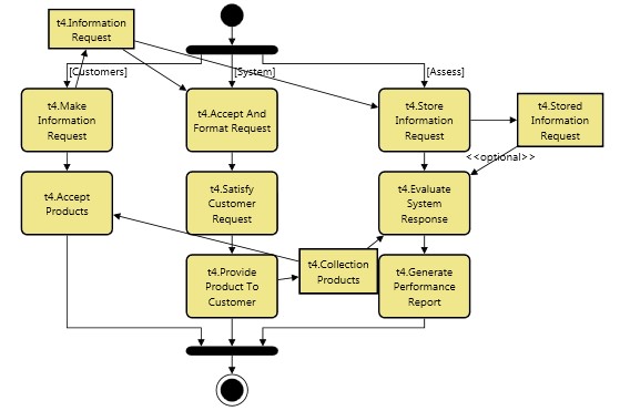
Figure 1. SysML Diagram
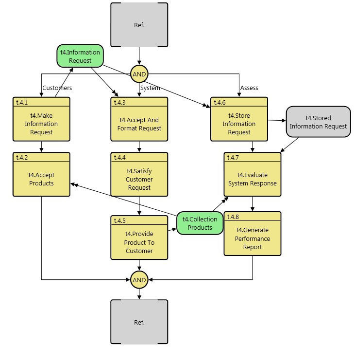
Figure 2. Enhanced Functional Flow Block Diagram
Activity Diagrams and Enhanced Function Flow Block Diagrams (EFFBD) such as this one are aptly described in One Model, Many Interests, Many Views, by Vitech’s Zane Scott and David Long. I have drawn heavily from this paper in the paragraphs that follow.
The Figure 1 SysML activity diagram shows the flow of data through functions depicted in swim lanes. In this example, we have Customer, System, and Assess. The rectangles on an activity diagram but not in the swim lanes represent the items or the data interaction aspect of behavior. (Note: The rectangle box at the far right, “t.4 Stored Information Request”, is a data store depicted by <<optional>>). Data stores are input to or output from a function with no control implications. Items that are input to a function are drawn with a standard arrow to that function, and in SysML have a label decoration indicating <<optional>> at the point of connection with the function. Triggers control the execution of a function. Triggers can be simple signals or actual objects. Items that trigger a function are drawn with a standard arrow to that function with no additional decoration as seen in “t4. Information request” and “t4. Collection Products”.
The Figure 2 Enhanced Function Flow Block Diagram (EFFBD), which shows the flow of data through functions, is also depicted via swim lanes Customers, System, and Assess. However, in an EFFBD, the data flows and triggers are rounded rectangles and are color-filled. The data store is a rounded-edge rectangle shaded gray, and data stores are input to or output from a function with no control implications and drawn with a standard arrow. Triggers, when present, control the execution of a function and are rounded-edge rectangles shaded green, drawn with a double arrow, and input to a function.
Wikipedia describes Systems Modeling Language (SysML) as the following:
a general-purpose modeling language for systems engineering applications. . . SysML is defined as an extension of a subset of the Unified Modeling Language (UML) using UML’s profile mechanism.
Although SysML is described as “general purpose” here, in my experience many people become overwhelmed by the complexity of the SysML language. Furthermore, most of the stakeholders and reviewers of a design are usually not SysML-savvy. Due to a lack of training in the SysML modeling language, they do not understand the data presented in that standard. This can lead to multiple questions on the design and information origins. This in turn can lead to a number of follow-up meetings to explain disconnects to individuals or teams. This is okay, but there is another way.
A solution can be found by using Enhanced Function Flow Block Diagrams (EFFBD)—exclusive to CORE and GENESYS software. By and large, in the training classes I teach, my students really like the methodology of the Enhanced Function Flow Block Diagram and are enthusiastic about creating those diagrams in the tool. The students tell me the eye tracks better to color than word decorations.
Communicating with the project community can be enhanced when you choose to demonstrate using tools that best generate understanding and deliver the artifact needed for a well-engineered design. GENESYS and CORE provide both SysML standard views as well as cousins to the SysML views (such as EFFBD diagrams), which communicate the same data and behavior in a less ambiguous way. I have found that Vitech’s diagrams are generally better understood by the reviewing community. And, since all the data required by SysML is captured, those who need or want SysML diagrams can avail themselves of the same.
This allows us to move forward in an environment that encompasses the best of both worlds: SysML standard views, and the ease and relatability of EFFBD diagrams. Now I call that a win-win.


