

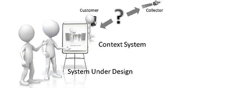
We often talk about understanding the three systems involved in the design space: the system under design, the context system, and the designing system. These three systems are depicted in Figure 1 from Vitech’s MBSE Primer, shown below.
As the illustration makes clear, 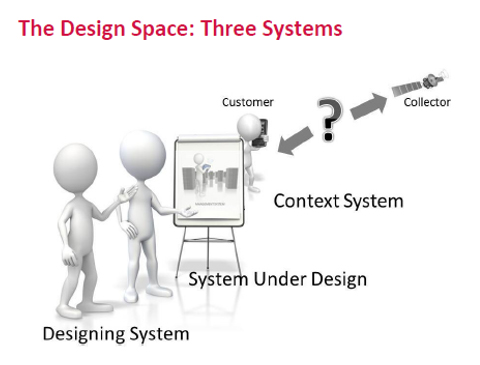 not only does the design team need to consider the system under design, but it must also consider the context system in which it will operate. This is even true when the context is that of a system under test. Recently, I have had several conversations with representatives of organizations that are either planning for or conducting verification of systems and are struggling with the management of verification events. In these conversations, there was a lack of clarity about the need to consider the context system in which the tests are to be conducted in order to properly manage that context system for the testing or verification event.
When performing system verification, I think it helps for the system engineering team to apply the concept of multiple systems. What I’m talking about here are the “Designing System” (which applies when completing Verification), the “System Under Test” (an instance of the System Under Design configured to support testing), and the “Test Context System” (the testing environment for the Verification Event being executed).
To explore this concept further, we turn our attention to the key classes and relations of the verification facility. We normally think of the classes in this facility from the perspective of system requirements and examine the methods for completing verification of these requirements. But, for the purpose of this discussion, let’s look at the classes from the perspective of managing the verification events.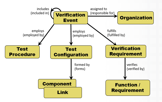
The Test Configuration supporting a particular Verification Event is formed by the System Under Test and the Test Context System taken together. For example, if we were testing a new vehicle at a test track facility, the Test Configuration would consist of a version of the vehicle and the test track facility.
However, we would likely go a bit further in understanding the test. The new vehicle, for example, might include a test interface link so that the test track facility could monitor vehicle performance. And, the test track facility would likely include a track command and control unit where the test information could be stored and reviewed in real time.
So, we might have a configuration that looks like the following: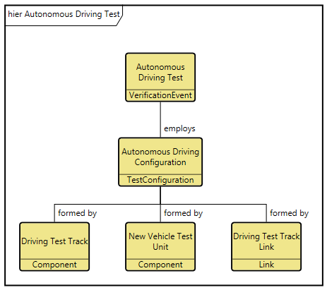
Applying the concept introduced at the beginning of this article, the New Vehicle Test Unit is the System Under Test. And, the Test Context System is composed of the Driving Test Track and the Driving Test Track link. This now properly frames the context system for a given verification event. We can continue this line of thought and consider the multiple configurations needed for the System Under Test and the Test Context System to manage the full set of verification events.
Extending this discussion further, the program office you are working in may also have the responsibility for managing a test track facility where various types of vehicles can be tested. In this case, your project team would likely also have a design architecture for the test track itself. If this is the case, we can use the cross project capability in GENESYS and CORE to model the facility architecture, the various vehicle product lines produced by the company, and the interrelationships between the vehicle product lines and the track facility to effectively manage verification events.
Now, let’s look at testing Vehicle Version A on the test track by performing the “Vehicle A Autonomous Driving Test.” In this case, I have two projects, one for the design of the Test Track and one for the design of Vehicle Version A. 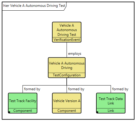
In this diagram, the Test Track Facility component and Test Track Data Link have been linked from a separate project in which I manage the architecture of the Test Track. (Note the small black square in the lower left hand corner of the icon.) These have been colored green to clearly differentiate that they come from the test track architecture. The remaining icons are part of the Vehicle A project and have retained the default tan color.
You can extend this modeling technique to reflect as much detail as needed. For example, the Test Track Facility may have multiple control facilities or multiple wireless test links with different capacities. If the objective of a particular Verification Event was to fulfill a Verification Requirement verifying a high-precision driving requirement, then the test configuration would be formed by a specific link and a particular set of high fidelity data recordings as well as a vehicle configured with a specific interface capable of a high rate of data communication.
Regardless of the level of detail you need to apply when planning and managing the verification of your system design, keep in mind the concept of multiple systems. Explicitly considering the System Under Test as well as the Test Context System will help you understand what things you must plan for and how to manage these items. Both the context system and the system of interest are critical to a systemic understanding of system operation – even when that operation is the performance of test activities.


