

The buzz in systems engineering today is all around supporting digital transformation. The focus has been centered on creating an “authoritative source of truth” and connecting the engineering lifecycle. As we accomplish system design and development, particularly in the model-based systems engineering (MBSE) environment, we are supporting the concept and development stages in the system lifecycle.* The lifecycle then transitions into production, followed by utilization and support, then, finally, retirement stages. To support the overall goal of connecting the MBSE model to the follow-on stages in system lifecycles, we need to be able to connect the descriptive model to the production system.
The physical system is created (or produced) through an implementation process wherein either a unique item is fabricated or a commercially available item is used to fulfill the function and requirements of the item specified in the model. As a first step in supporting the digital lifecycle, we should be able to capture the descriptive information contained in the MBSE model and relate the model to the first version of the system, generally referred to as the “as-built” version of the system elements. What follows in this article is a description of how the model-based system engineering environment in CORE or GENESYS can be extended to support identification of the “as-built” instance of the system.
As the system is developed, the physical architecture of the system is defined from the top-level system description down to the configuration items that make up the complete system. An example of such a physical breakdown is represented in the structure block definition diagram, as shown in the following illustration.
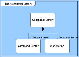
Figure 1. Typical Structure bdd
This diagram shows the decomposition of the system into two subsystems. The subsystems in turn would be broken down into a subsequent level until we get to configuration items, the lowest level of the system decomposition that allows us to either fabricate the items or purchase commercial items, thus fulfilling the requirements and functionality of the configuration item. In other words, the defined system configuration item is instantiated by a particular physical item—the hardware piece or software code that fulfills the purpose of the item in the architecture.
The instantiation of the system by virtue of the products selected to meet the physical architecture is shown in another type of block diagram, the classification bdd. (In CORE and GENESYS, relating the instances of a component uses the relation “generalization of/kind of”.) It is common in industry to have multiple configurations or “models” of an item. In the diagram below, the abstract Geospatial Library is instantiated or realized by two different models: Geospatial Library Model A and Geospatial Library Model B.
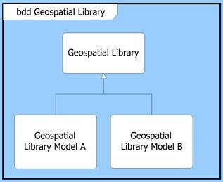
Figure 2. Two Models for the Geospatial Library
Model A and Model B are two separate configurations of the Geospatial Library. Taking this concept further—because the Geospatial Library is composed of a Command Center and a Workstation (as depicted in Figure 1)—we can have two or more configurations of the Command Center.
Whether the Command Center is fabricated or procured, we generally give these items an identification label. For the purposes of our discussion here, I will call this identification label a “Part Number”. Your industry may use a different term here; the main point is that we have an identifier for the multiple instantiations of the abstract component. Adding this attribute to the model schema provides a way for us to identify and track various configurations of a block in the architecture.
In the diagram below, we show two versions or the Command Center, each with a unique part number.
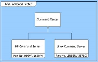
Figure 3. Two versions of the Command Center
Both the “HP Command Server” and the “Linux Command Server” may be used as a Command Center in the overall system configuration. Each of these instances of the Command Center may have unique requirements or internal configurations, and these can be documented in the system model in the same way the Command Center is specified by requirements, functions, and interfaces.
We can represent varying models of the system with unique configurations by using the classification bdd adding the Part No. attribute to identify the configuration. An example of the Geospatial Library Model A is provided in the following diagram.
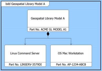
Figure 4. Configuration of GL Model A
The ability to capture the various configurations of the components in the model, together with the addition of the Part No. as the unique identifier for the configuration, gives us the ability to document the “as built” architecture for the production stage of the lifecycle. These key pieces of information provide the reference point for the ability to track the product through the subsequent utilization, support, and retirement stages of the lifecycle.
*See ISO/IEC/IEEE 15288:2015 for a complete description of the activities required in the concept and development stages of a typical system lifecycle.


