

When teaching classes on model-based systems engineering, I am frequently asked about methods to manage different system configurations in the model. Most engineers are very comfortable thinking in part structures, and while this is a critical aspect of systems engineering, it’s not the whole story. To answer the question and manage variants, we leverage the generalization/kind of relation in parallel with part structures.
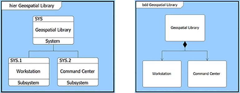
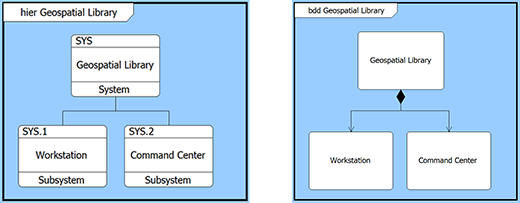
Classical systems engineering is concerned with the decomposition of our physical architecture (the bill of materials). In the Component class, this decomposition structure is captured using the parent-child relation built from. A system is built from its subsystems, and those subsystems are built from their constituent parts. An automobile is built from its chassis, drive train, engine, and more. In the Geospatial Library example provided with CORE and GENESYS, the Geospatial Library (the system of interest) is built from the Workstation and Command Center subsystems.
Graphically, the decomposition of the physical architecture is shown in a classic physical hierarchy or a SysML structure block definition diagram (BDD). Both diagrams represent the built from parent-child relation.
As we move beyond decomposition and begin to look at commonality (and eventually variant management), we move from parent-child relationships to other concepts. Going back to our early scientific education, we may recall the classification of living things where we organize the animal kingdom in phylum, subphylum, class, order, family, genus, and species. The same concept applies to the systems we architect, analyze, and build, bringing key value and insight alongside composition.
To reflect this concept of inheritance, we use the generalization/kind of relation. The concept of a more general/abstract object and a more specific object applies to many different classes of elements – requirements, functions, items, etc. – but it is easiest to conceptualize and most commonly used in physical architecture. The more general element is the supertype. The specialized element is called the subtype. Going back to our automotive example, a supertype could be sports car, with specific automobiles (Corvettes, Camaros, and Mustangs) being subtypes. For an engine, the subtypes could be characterized by type (gas vs. hybrid vs. electric) or physical characteristics (number of cylinders, displacement, horsepower).
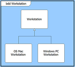
In the case of our Geospatial Library example, let’s consider two configurations for a workstation: one workstation uses a Windows-based PC and one workstation is an OS-based Mac computer. The Workstation element (representing the generic workstation) is a generalization of two elements which I have chosen to name “Windows PC Workstation” and “OS Mac Workstation.” When reading from the subtype we would state “The Windows PC Workstation is a kind of Workstation subsystem.” The classification block definition diagram reflecting this inheritance structure is shown as follows:
In dealing with subtypes and variants, we often want to highlight the behaviors and characteristics that define the individual elements. In the case of physical components (or blocks), we can define operations and receptions behaviors of both the supertype and subtype to better understand characteristics of these objects. Operations represent a behavior that a component does when it is called. A reception, on the other hand, is a behavior performed when triggered by some event. The operations and receptions attributes (on the secondary tab of the property page in CORE) allow you to define these aspects of components. You can add an operation or reception using the defined syntax from SysML or add the string in a project-specific format.
Another characteristic of interest is values information. In CORE and GENESYS, these are the parameters defined for the element.
While operations, receptions, and values (parameters) are captured as part of the properties of a component (block), this information can also be shown on the diagrams to enrich the representation and communicate more information. As always, it’s important to tune the diagram to the intended audience and purpose so that you properly inform – but don’t overload – the reader. You can strictly follow the format and syntax of SysML, or you can follow a project or company tailored format. An example of a tailored format is provided in the following diagram showing receptions and values for the supertype and subtype elements.
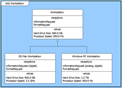
In this example, the Workstation supertype has a set of values reflecting the hard drive size and the processor speed. The two subtypes have different values, each of which meet or exceed the values required of the supertype. This is an example of using a commercial-off-the shelf (COTS) product to fulfill the needs of the Workstation.
Two important concepts must be kept in mind when representing more than one configuration of an element in an architecture: abstraction and specialization. We create generalizations in the architecture to show an abstraction of the subtypes. This lets you, as the design engineer, define the common features of the generic component. This means that all of the features of the supertype flow down to each subtype. As such, this abstraction conveys the “substitutionability” of the element, which means that any of the subtypes can be used wherever the supertype is called out in a design.
In contrast, a subtype may have additional features over and above the features required of the supertype. This is the concept of specialization, meaning that the subtype has special features or qualities not represented in the supertype.
Additional reading on this topic can be found in two reference books:
- SysML Distilled, A Brief Guide to the Systems Modeling Language by Lenny Delligatti, Addison-Wesley, © 2014.
- Systems Engineering with SysML/UML Modeling, Analysis, Design by Tim Weilkiens, OMG Press © 2006.


