

By Ron Kratzke, Principal Systems Engineer
GENESYS 4.0 introduced two new diagrams – the Constraint Block Definition Diagram (BDD) and Parametric diagram. The addition of these two diagrams opens and expands insight into system design. The Constraint BDD graphically displays the parameters restricting or constraining system design. The Parametric diagram graphically displays the mathematical relation of the parameters constraining system design.
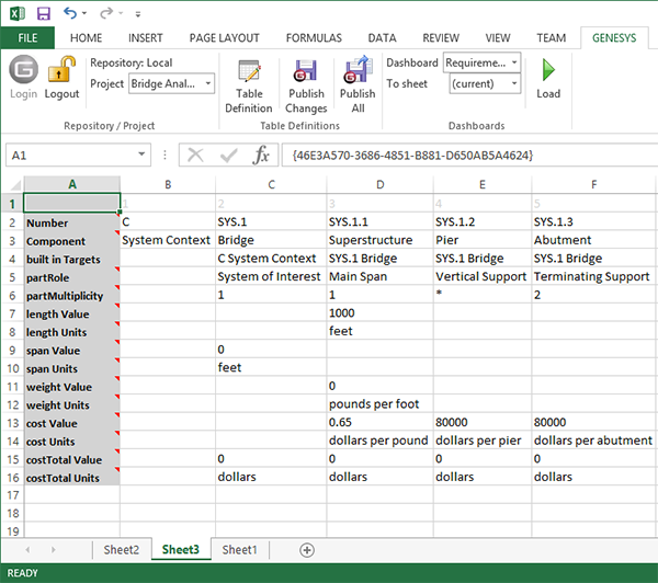
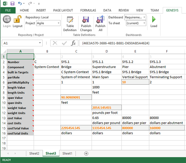
The process of creating these diagrams begins by identifying the parameters constraining a component in the system. The ability to express parameters related to system entities was provided in earlier versions of GENESYS. Parameters can be uniquely defined in a class and the value of any parameter uniquely defined for any individual entity.
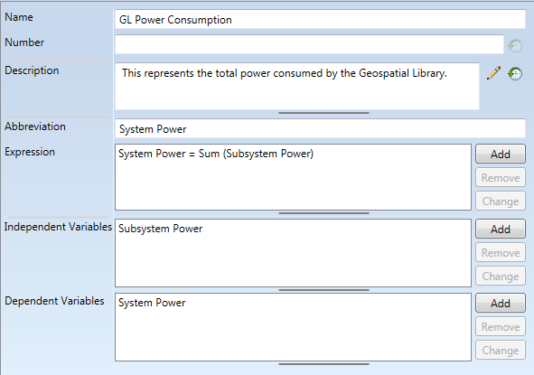
Start the Parametric diagram by defining the parameters that constrain a Component. Once defined, the system engineer relates the Component to a ConstraintDefinition (a new Class in GENESYS 4.0) using the “constrained by” relation (Component “constrained by” ConstraintDefinition).
The ConstraintDefinition is a representation of the mathematical expression for the parametric constraint defined in the related Component. A typical ConstraintDefinition is shown below:
With the ConstraintDefinition defined, the design team can then express the system constraints in two diagrams: the Constraint BDD and the Parametric Diagram.
The Constraint Block Definition Diagram is drawn from the perspective of the Component. The diagram shows the “constrained by” ConstraintDefinition for the Component. A ConstraintDefinition may be further defined by additional ConstraintDefinitions using the “includes constraint definition” relation. A typical Constraint Definition Diagram is shown below.
The ConstraintDefinition entity allows for the creation of the parametric diagram by graphically showing the relation of the constraint definitions and the parameters constraining the Component. The parametric diagram below shows the relation of the subsystem power consumption to overall system power consumption.
This schema extension in GENESYS and the ability to render the Constraint BDD and the Parametric diagram, together with their relation to the basic system design entities greatly enhances the system engineer’s ability to define, document, and demonstrate the complex nature of the system. These diagrams also provide the connection points to specific analytical and optimization models for the system.


