

By Ron Kratzke, Vitech Principal Systems Engineer
Recently I have fielded several questions regarding the use of the State Transition Diagram in CORE and how States/Modes and the diagram relate to system behavior and simulation of the system behavior using CORESim.
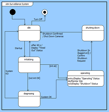
State transition diagrams describe the logical transition of a system through various states of operation. Presented in a freeform layout, the state transition diagram represents states, the transitions that connect them, and the events that trigger transitions. The implementation of the diagram in CORE aligns with the SysML representation.
States are an orthogonal approach to looking at the behavior of a system and is a higher level abstract way of understanding the behavior of the system. Some systems are well suited to a state transition representation, and many individuals naturally think this way. Other systems are well suited to a behavioral representation, and many naturally think in this pattern. Ultimately, it’s up to the team and the individual whether to use state, behavior, or both in their analysis and modeling. If both are used then states, their transitions, and the related events are higher-level concepts that are realized by behavior.
System behavior, of course, is the fundamental basic way to look at the system or component functionality. And, all CORE users are familiar with the techniques in CORE for developing an EFFBD or Activity diagram to capture and document this behavior.
In the CORE schema States, Modes, and Events are related to the system behavior using a series of relations. A Mode is “contained by” a Component; a State “incorporates” a Function; and, an Event is “responsible for” and Item.
These unique relationships allow the system design engineer to navigate thru the system design from a particular state to the fundamental function supporting the state. The function, then, is what can be executed in CORE. The relation alignment enforces consistency and completeness of the system design by ensuring that a State is not defined without a corresponding function assignment.
After all, we would not, as system design engineers, want to define a state of operation for a system or component without ensuring the definition of the behavior (or functions) that support that state.
For more information on the State Transition Diagram, be sure to explore the CORE help files and the MySupport Skill Building Screencast Library.


