

When you are developing a system design, have you ever asked yourself how it will be implemented? As systems engineers, we must always keep in the back of our minds that someone will have to print or manufacture parts, assemble and integrate subsystems, and eventually maintain the system. We can easily overlook details of integration and maintainability as we focus on meeting customer requirements.
On one of my projects, great attention was given to the breakdown of the system into its constituent sub-systems, assemblies, and parts and ensuring that the design met all requirements and performed necessary behavior. It wasn’t until mid-way through the design process that we began to think about how the system was going to be installed, operated, or maintained. Needless to say, we had to rework the design. Effective distances between parts of the system, racks for equipment, details of networking—all came into greater scrutiny.
As systems engineers, we know that in traveling from abstract notions of the system boundary and major sub-systems all the way to the bill of materials, system design covers a lot of territory. We tend to gloss over the details and focus on customer requirements and high-level design. Our engineering colleagues doing detailed engineering, on the other hand, are focused on implementation or fabrication, and don’t have the opportunity to consider the big picture. The key is to keep all perspectives in mind. Here are some suggestions and ideas to consider in dealing with design.
Identify the Abstract Design
If you use a top-down methodology, identifying the high-level and then preliminary designs is where we are most comfortable. The key is realizing that the design is only half the battle. We tend to start by defining a system boundary and identifying external systems and interfaces and then proceeding to build out the system in terms of its segments, sub-systems, and assemblies. We eventually reach a detailed design that becomes more concrete and physical. We may model this detailed design with our MBSE tools. But CAD drawings become necessary the closer we get to implementation, when detailed engineering is involved.
The same is true if you are following an iterative methodology that continually refines requirements. Keep in mind that there will be more iterations (i.e. sprints) than you might think at the outset if your system is cyber-physical. I’ve seen projects that develop great software, but forget they need to integrate equipment and provide shelter and transportation systems.
The abstract design consists of the system and subsystem design with particular attention paid to interfaces and connections. It can be very detailed, specifying specific hardware parts, but until implementation matters are considered, it is not yet quite complete.
Consider the Implementation
At each level of decomposition in your system design, stop to think about how the design might be implemented or maintained, and consider the implications on requirement specifications. You can reconsider whether your functional behavior is better allocated differently among system components, or you may consider the implications of where parts of a sub-system might be installed upon system interfaces. I’ve seen systems where cameras and sensors are installed in one shelter or housing, and the processing systems are installed in an entirely different shelter or housing with implications for interfacing and connectivity. Also, available footprints may constrain the size or weight of a component or assembly. Requirements may need to be derived to fully capture or specify the systems design. New environmental requirements or SWaP (size, weight, and power) requirements may be necessary, or interfaces may be affected. Cabling and electromagnetic interference hardening may be required that were not fully considered at the outset of the project.
Special Considerations
A lesson learned here is: Don’t confuse interfacing with decomposition. A subsystem component may be installed in a rack, but the rack is not the subsystem, it is just another assembly. Another example is when parts of subsystem A are installed in subsystem B. The installation points are really interfaces between parts of subsystem A and parts of subsystem B; the parts of subsystem A are not decompositions of subsystem B.
Another point of confusion is when a collection of assemblies from different subsystems are aggregated together for purposes of integration. A good example of this is the typical “bench” or “bus” hardware where assemblies from inter-operating subsystems are installed. It is easy for engineers, including systems engineers, to confuse the “bench” for a subsystem, but the bench is just a construct developed for purposes of integration; the bench is an assembly of the subsystem, it is not a subsystem in its own right.
It is useful then to develop installation drawings of your system in addition to the familiar block diagrams that describe the logical arrangement of parts. Be careful that you don’t mix perspectives on the same diagram, or your team may get hopelessly confused. Make sure you have separate drawings showing the abstract design and the integrated design. It’s OK to have a third perspective using a hybrid, fit-for-purpose diagram showing both abstract and installation design together, but it shouldn’t be the only view available.
MBSE for System Design
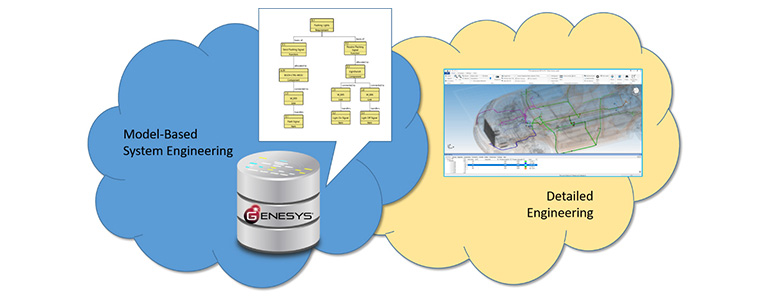
MBSE can assist both abstract and integrated designs and help connect the design to CAD tools for further elaboration of the detailed design. Using the Vitech systems metamodel, an abstract design of the system is depicted with the built in and built from relationships as shown in Figure 1. Keep in mind that you are still developing the abstract design and not the integrated design. As you move through the systems lifecycle, more detail will emerge.
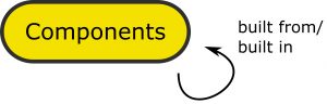
Figure 1. Developing a System Design
The integrated design is motivated with the use of interfaces. As depicted in Figure 2, Interfaces are a way to show where parts of a system design are joined. Links are a way to show how parts of a system design are connected. As I discussed in my recent webinar (MBSE 2.0 for Interfaces: Understanding Interfaces in a More Complex World), Interfaces are abstract, while Links can be both abstract and concrete.
Links don’t become concrete until you reach the lower levels of your system design. Links can represent physical cabling, hardware connections, or pipes. It is not until the detailed design stage that specifics of the cabling, nuts and bolts, or piping are designed. Also, relating Links to Interfaces using a comprises/comprised of relationship helps us to associate a series of physical connections (i.e. Ethernet cables, local area networks, wide area networks) with more abstract relationships (i.e. The External Users Interface, The Chilled Water Interface, The Power Interface).
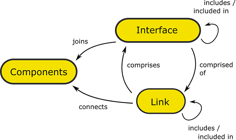
Figure 2. Identifying Interfaces
When considering how components may need to be installed, derive requirements that can drive new Functions or specify Components directly. As depicted in Figure 3, the systems metamodel allows for relationships among Components, Functions and Requirements. Additionally, Requirements have a type attribute that allows you to identify whether the requirement is an original requirement, or a derived requirement. Lastly, be sure to record your observations with a Concern to provide a rationale for creating additional design details and requirements to deal with implementation concerns.
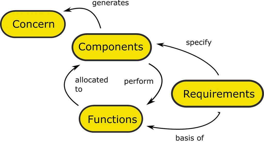
Figure 3. Identifying Functional and Constraint Requirements
Summary
The next time you are developing a system design, remember the implementation perspective and consult with specialty engineers to uncover implicit design details. A good system design should show both the abstract relationships of the components of a system as well as the integrated perspective of a system as it would be implemented and built. You may need more than one diagram to tell the whole story, or a hybrid diagram based on your MBSE model. Also, there will certainly be limits to what your MBSE tooling can achieve, so it is incumbent on you as the systems engineer to share or connect your MBSE model with detailed engineering CAD tools that will pick up where the MBSE leaves off. This means that you should use a systems modeling tool with an open API robust enough to handle the connection of the CAD tool generated data to the system model. Finally, remember that a rich systems metamodel is critical to expressing your systems design and facilitates integration of MBSE and CAD-like tools. When you fully consider all aspects of your systems design, you will help focus the efforts of engineers, thereby enabling better cohesion in your project.


